hi hi hi

hi hi hi
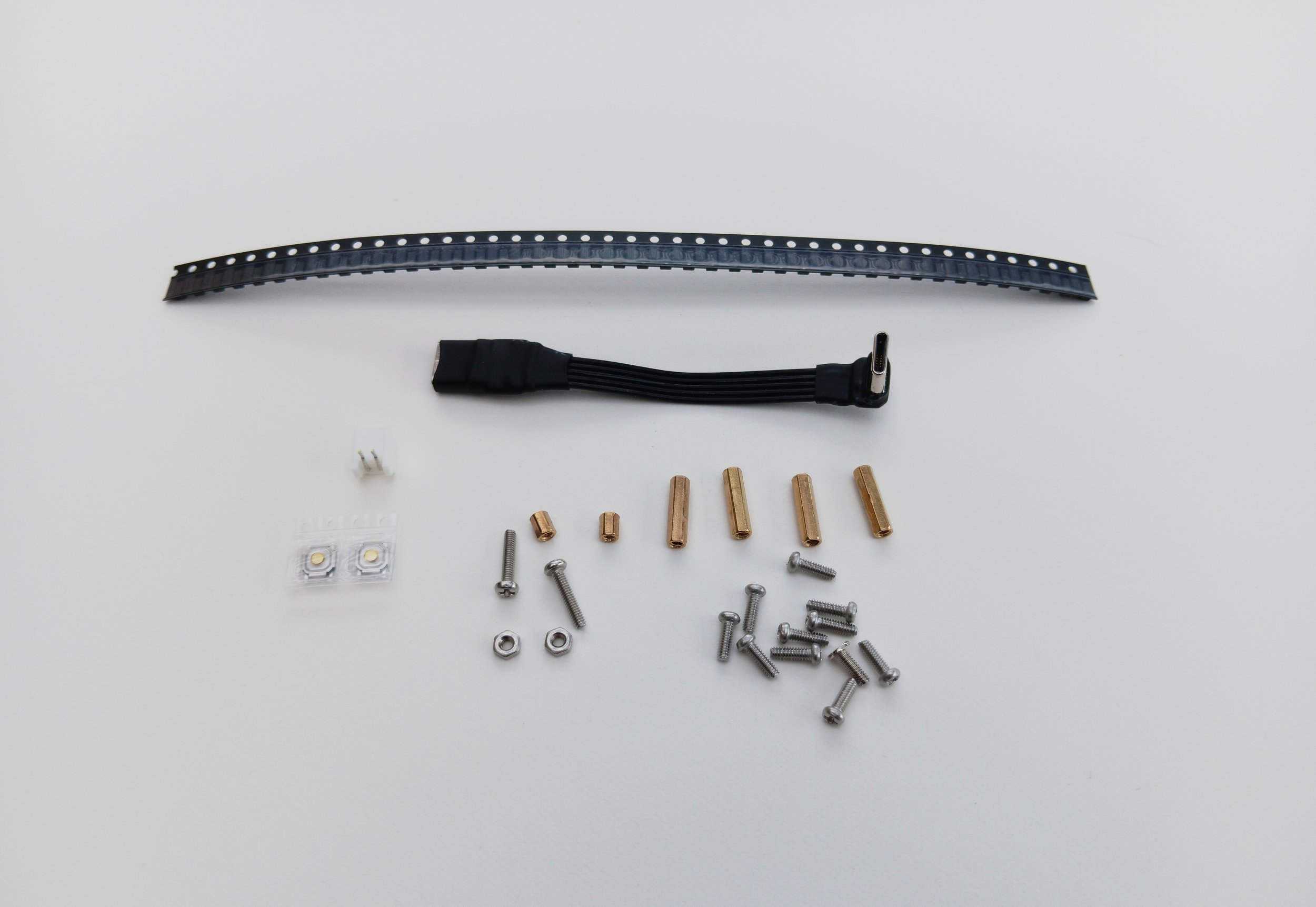
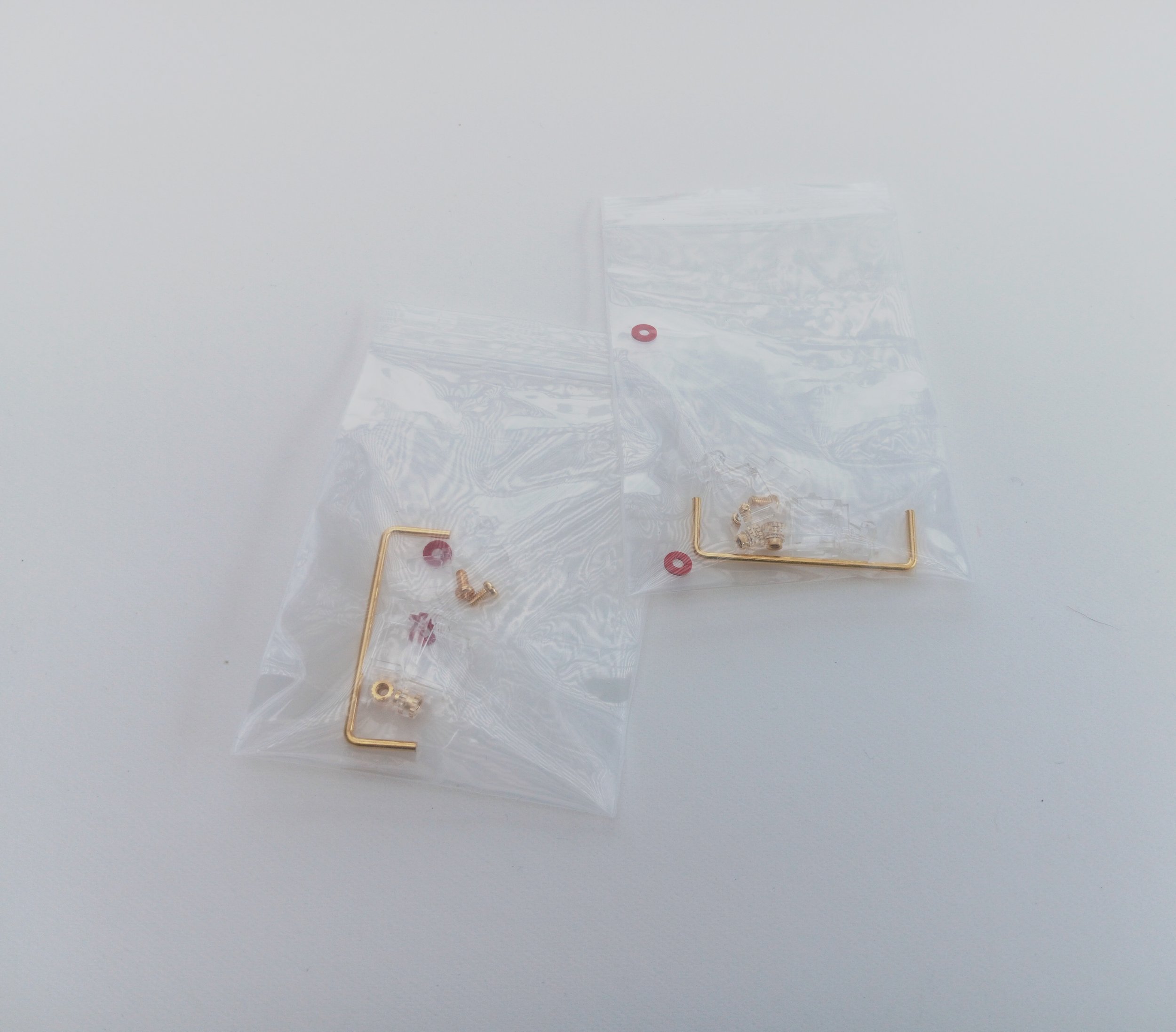
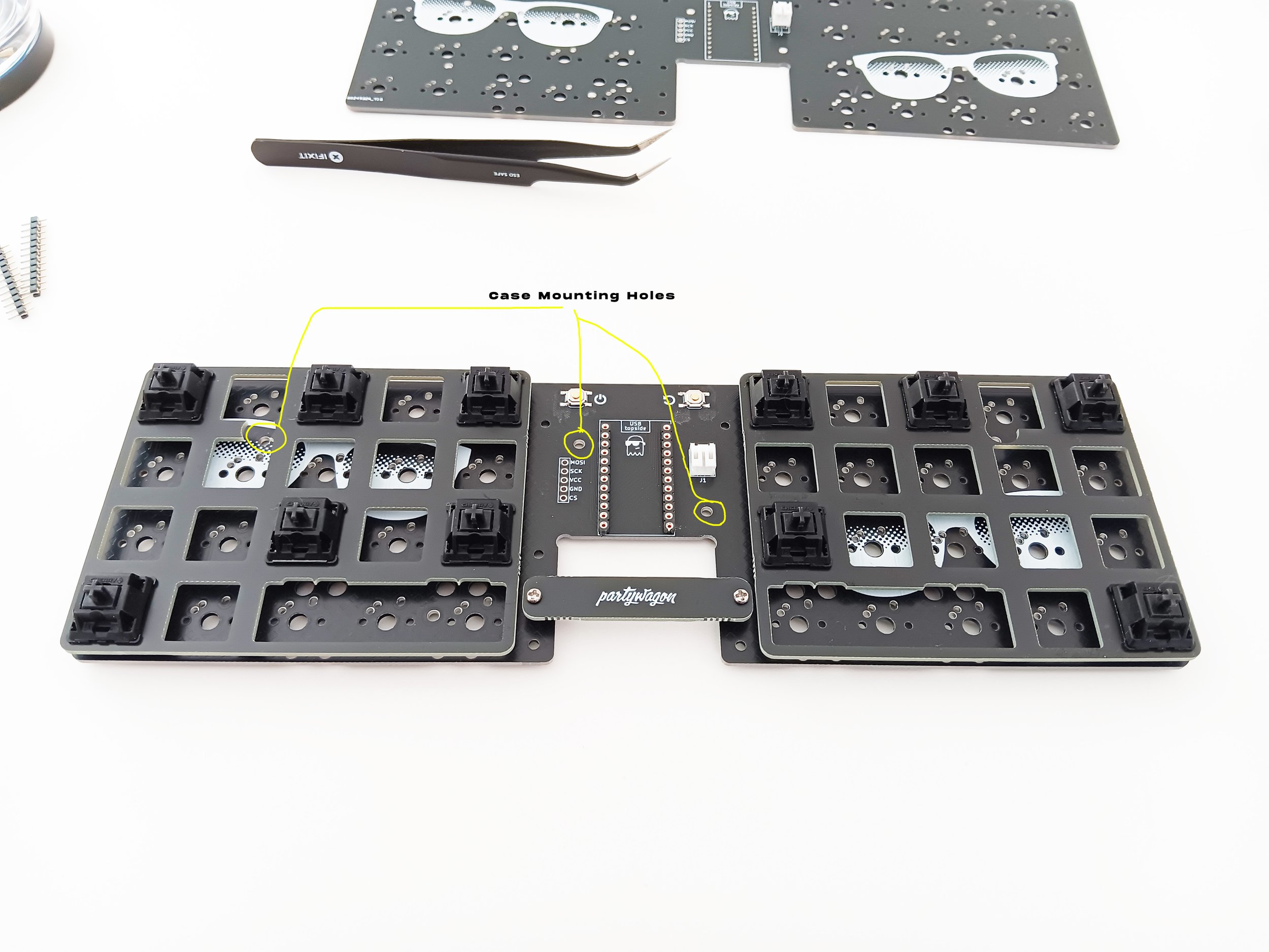
Check the contents of your build kit and make sure all the parts are included. Contact: thedude@spookydudestuff.com if you find any issues. Familiarize yourself with the PCB and identify which is the top and bottom side as parts will be applied to both sides during the build. The top side has the graphic of sunglasses and the bottom has the Partywagon text logo.

To build the keyboard kit you will need:
Soldering iron - I use the Pinecil and like the results. 325 C is sufficient for all steps.
Solder - 0.6mm works for everything (I use 1mm for the switches just because) - recommend leaded with flux core.
Flux - a pen or otherwise. No-clean, the smallest amount available.
Tweezers - ESD safe, angled tip, reverse action ideally.
Wirecutters - side cutters will small blades are optimum.
M2 phillips screwdriver
Safety Glasses/Goggles/Faceshield
Optional but useful:
File
Plastic spudger
Cotton swabs and rubbing alcohol
Tray to hold small bits
Masking tape if installing Millmax headers and pins
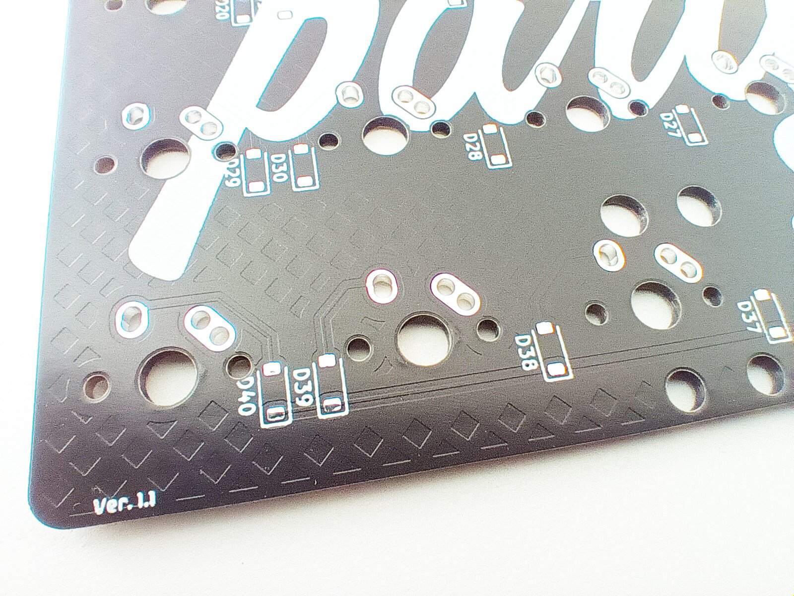
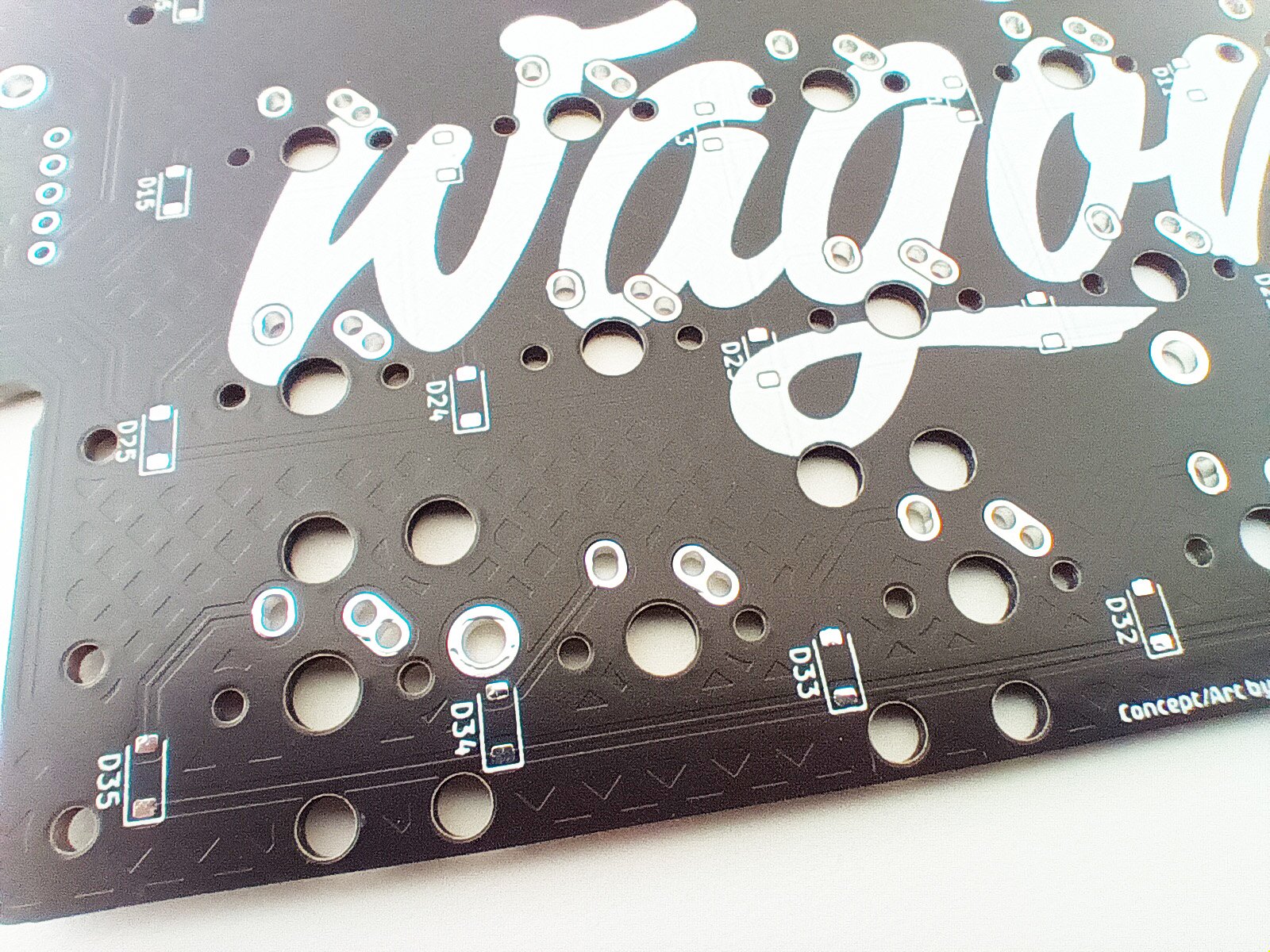
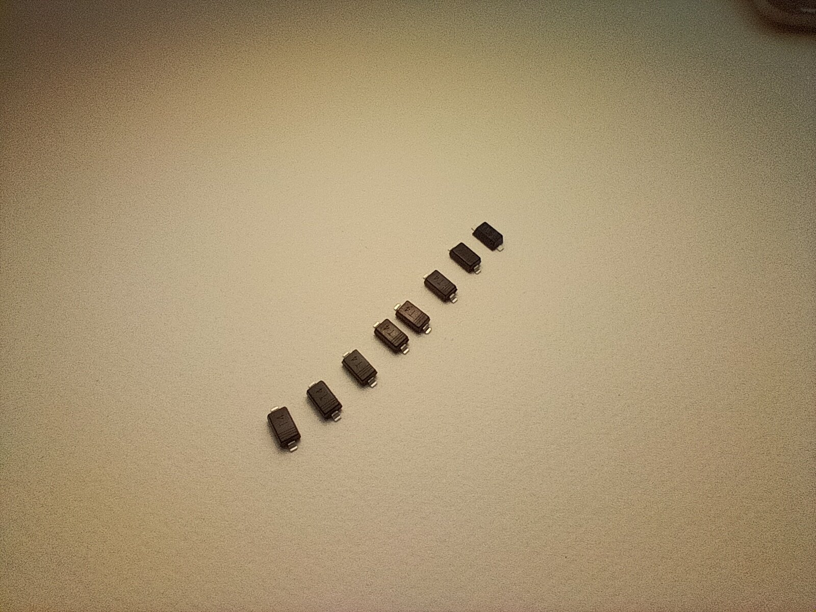
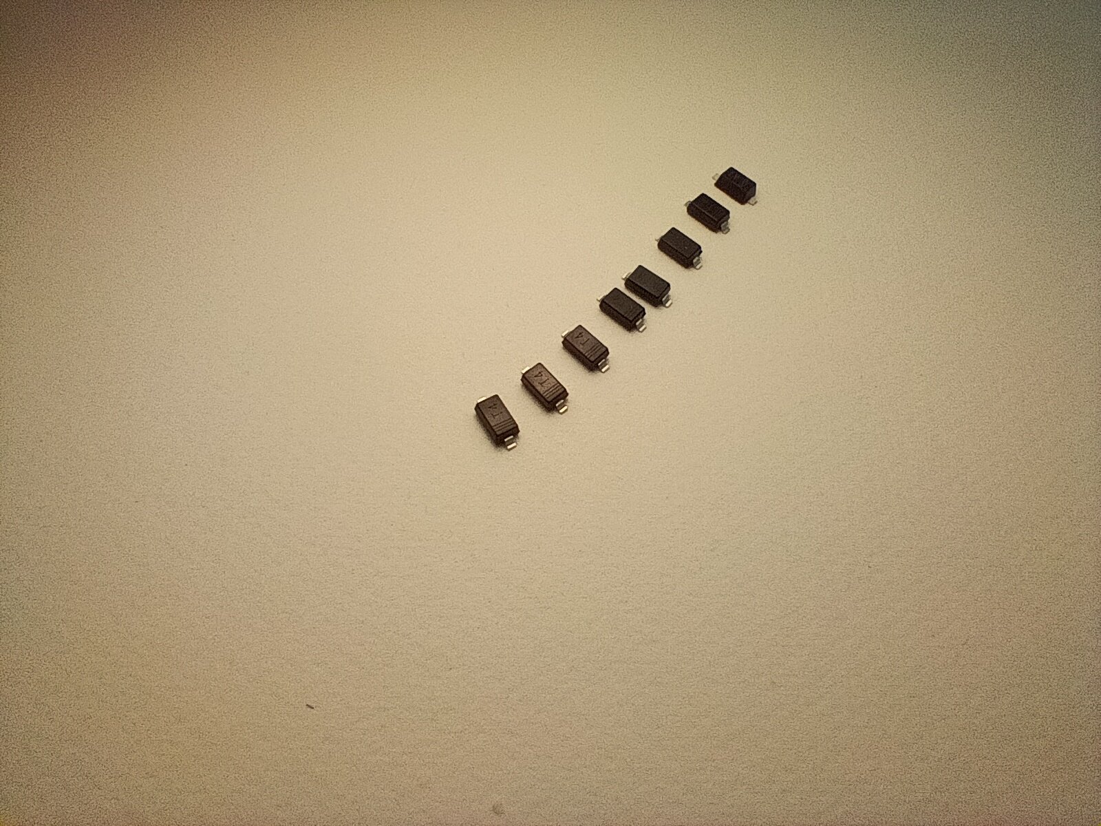
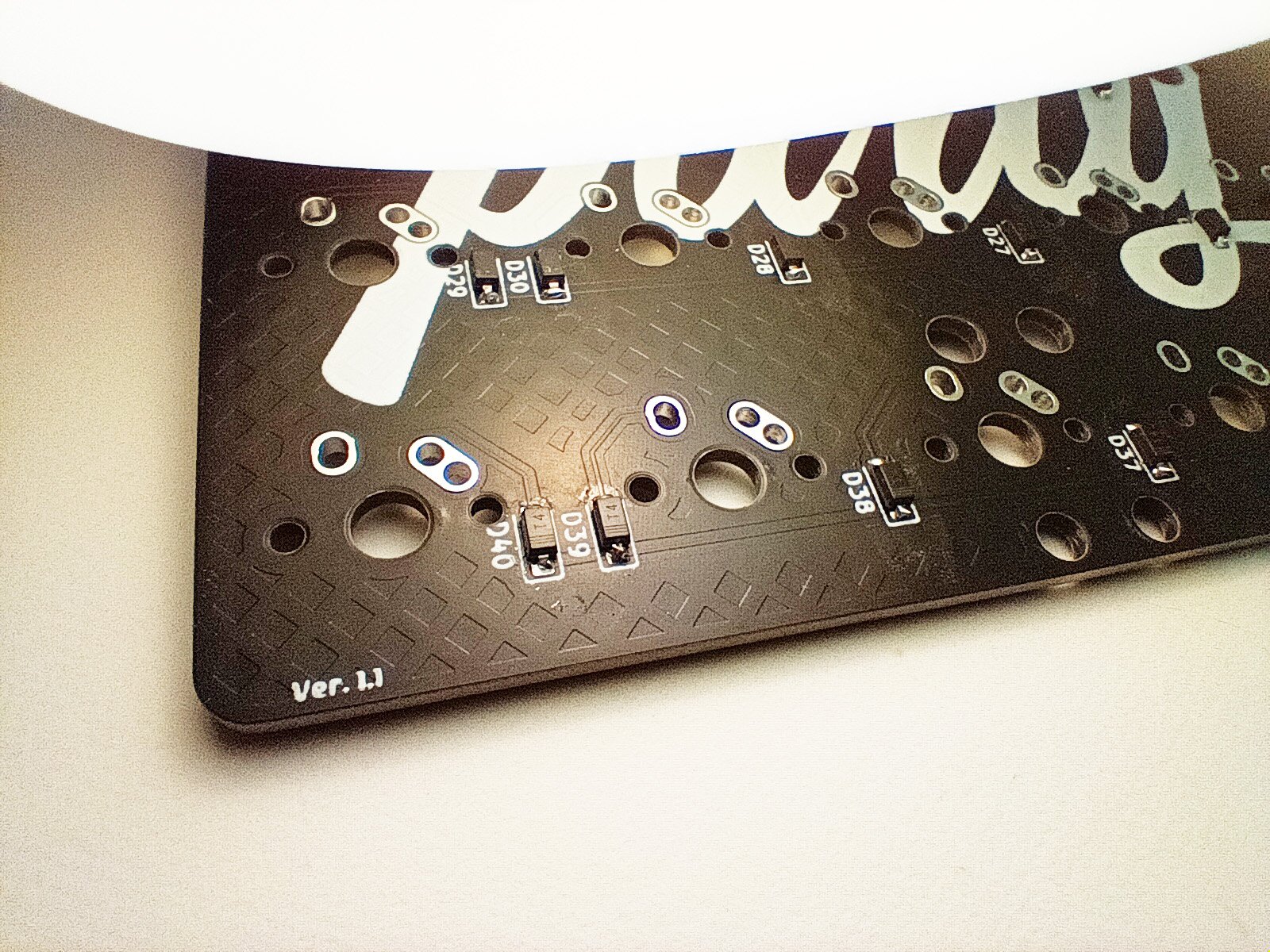
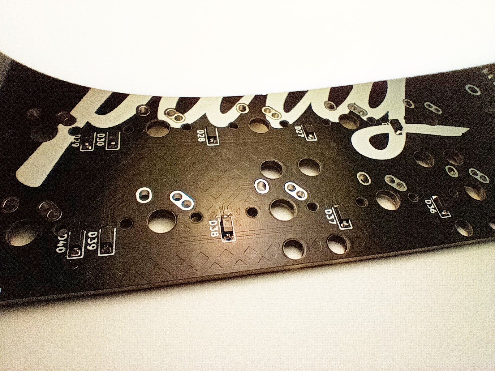
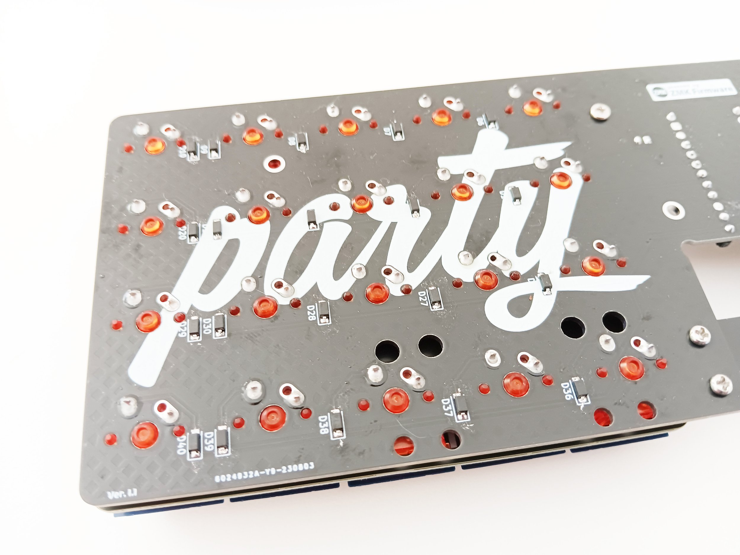
Diodes will be added to the bottom of the PCB. The orientation of these components is important. Find the pairs of pads labelled with “D” numbers, like “D3“ and “D35“. You will see a line on each diode that indicates it’s install direction. You will want the “D” numbers to be on your left and the diode lines to be nearer the bottom pad (see picture).
There are two popular ways to approach soldering these parts on. One method is to apply a blob of solder a single pad and hold the diode in place, then reheating the blob on the PCB so the diode can be pushed into it and in place. Another way to do it is by adding flux to the pads for the diode you want to apply, and then holding the diode in place while you add solder to your iron and rub/smear it onto the diode and pad letting the flux pull it into place.
At this point please double-check that all the diodes are oriented correctly. It is easier to free up an incorrectly positioned diode that is only soldered on one side.
Both of these ways require you to then go back to each diode and solder the other leg and pad together. I would further recommend returning to the original first legs and pads and add additional solder as a failsafe.
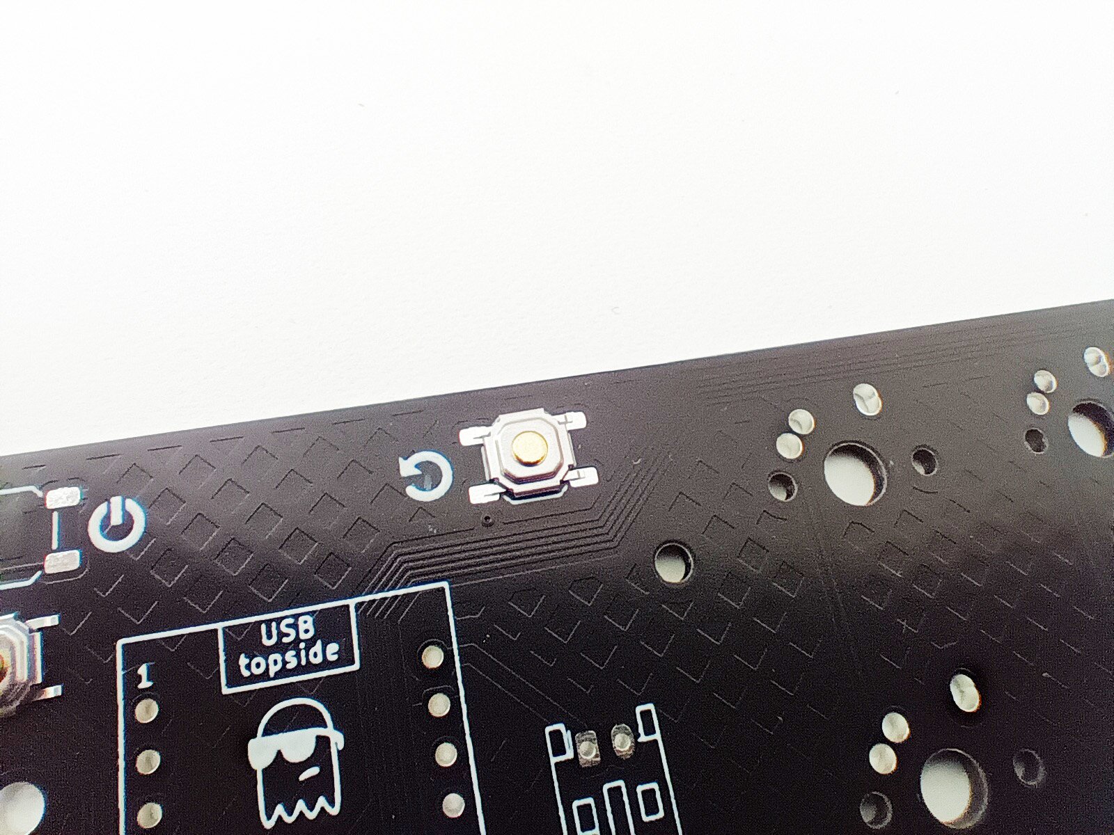
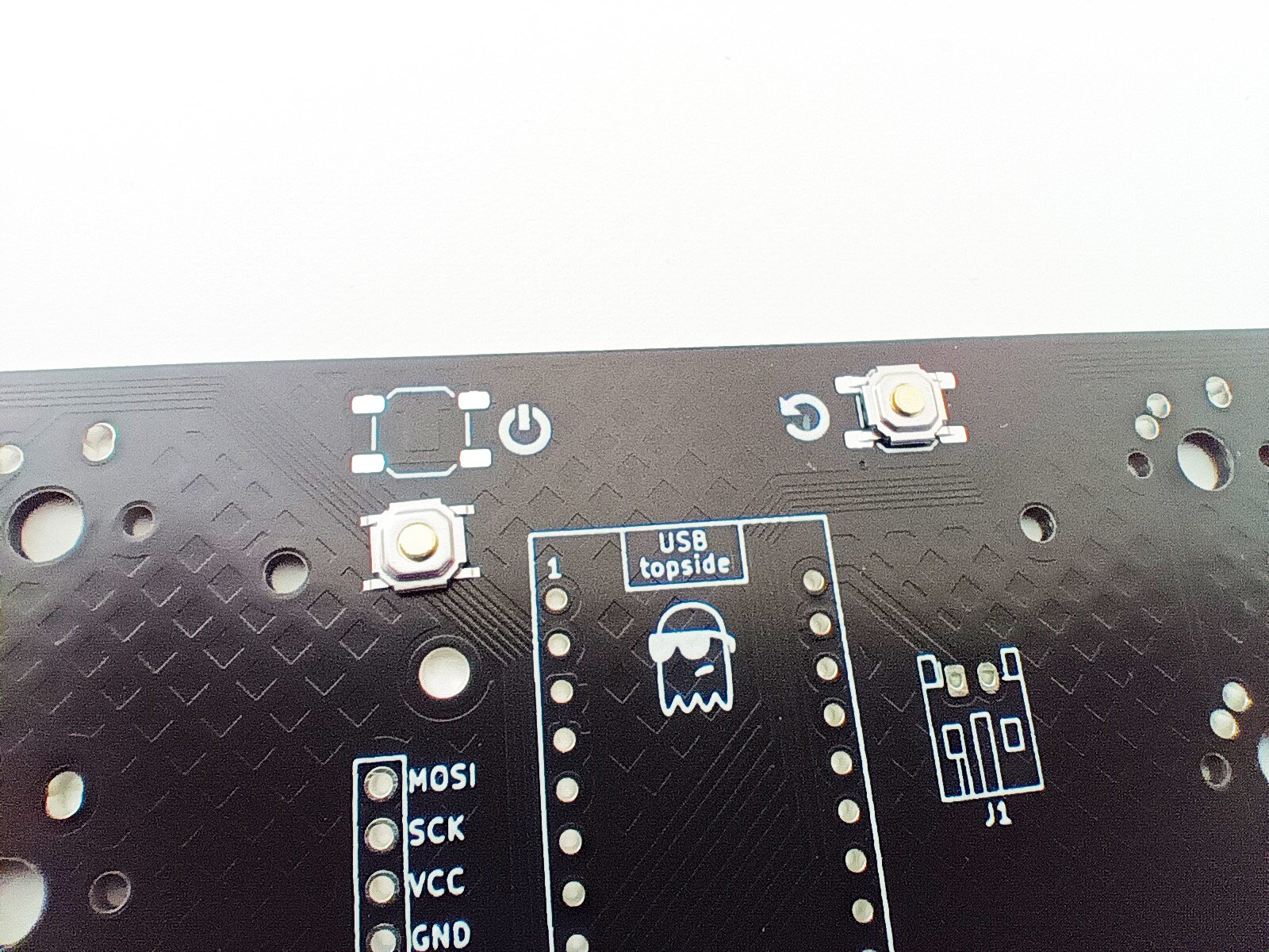
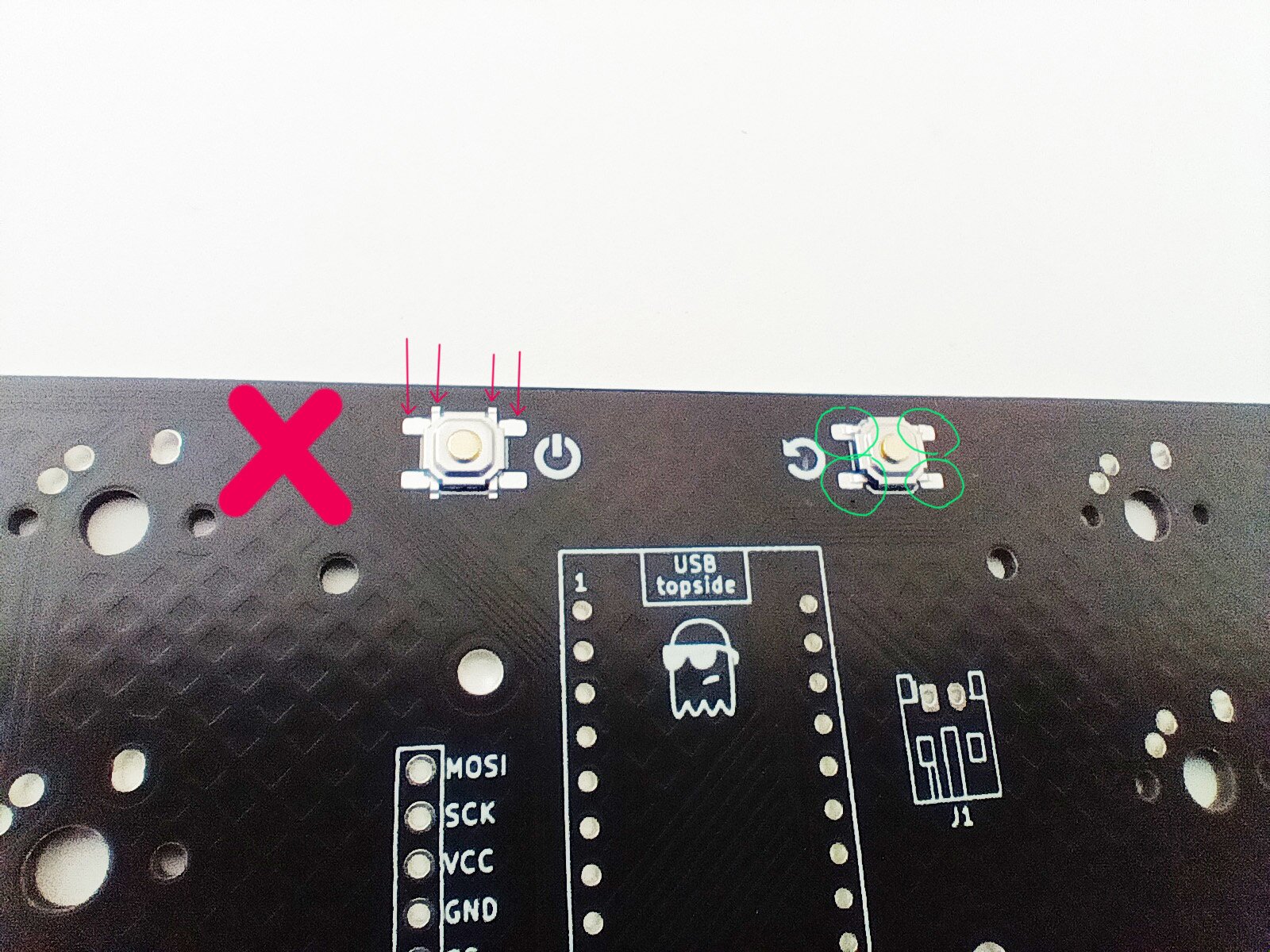
These components are mounted to the top side of the PCB, so flip it over and make sure the sunglasses art is face up. The orientation of the two buttons is important, so please refer to the images. They will only truly line up with the pads when correctly positioned.
Soldering of these can be done with either of the ways the diodes are done. The blob on PCB first is totally acceptable, but I do find these to be very easy to do with the solder loaded iron tip method. Check the switch position and hold it in place with tweezers while dabbing/smearing some solder onto the contact and pad. Remember to solder the remaining button connections before moving on to the next step. There is a total of four per button.
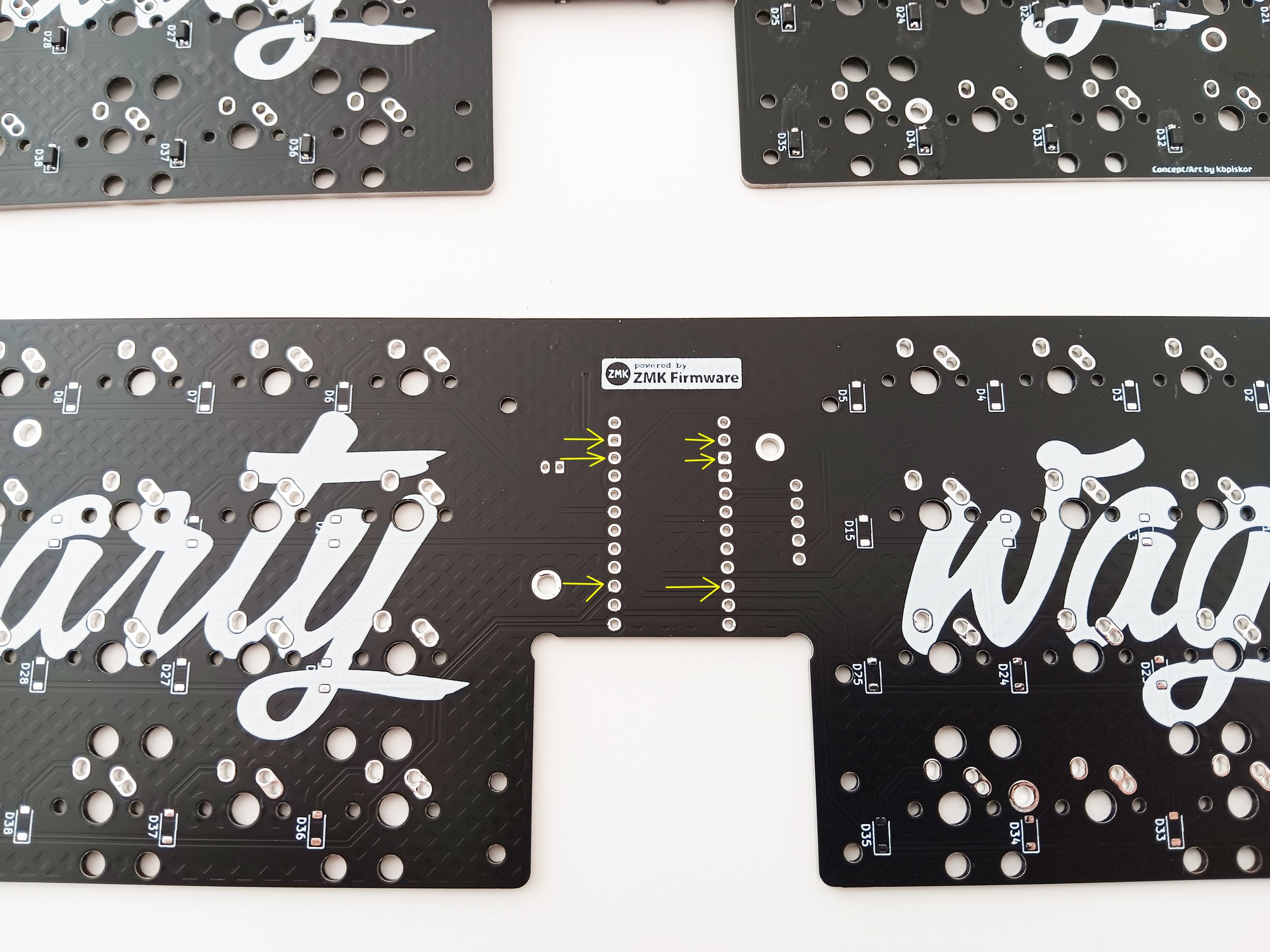
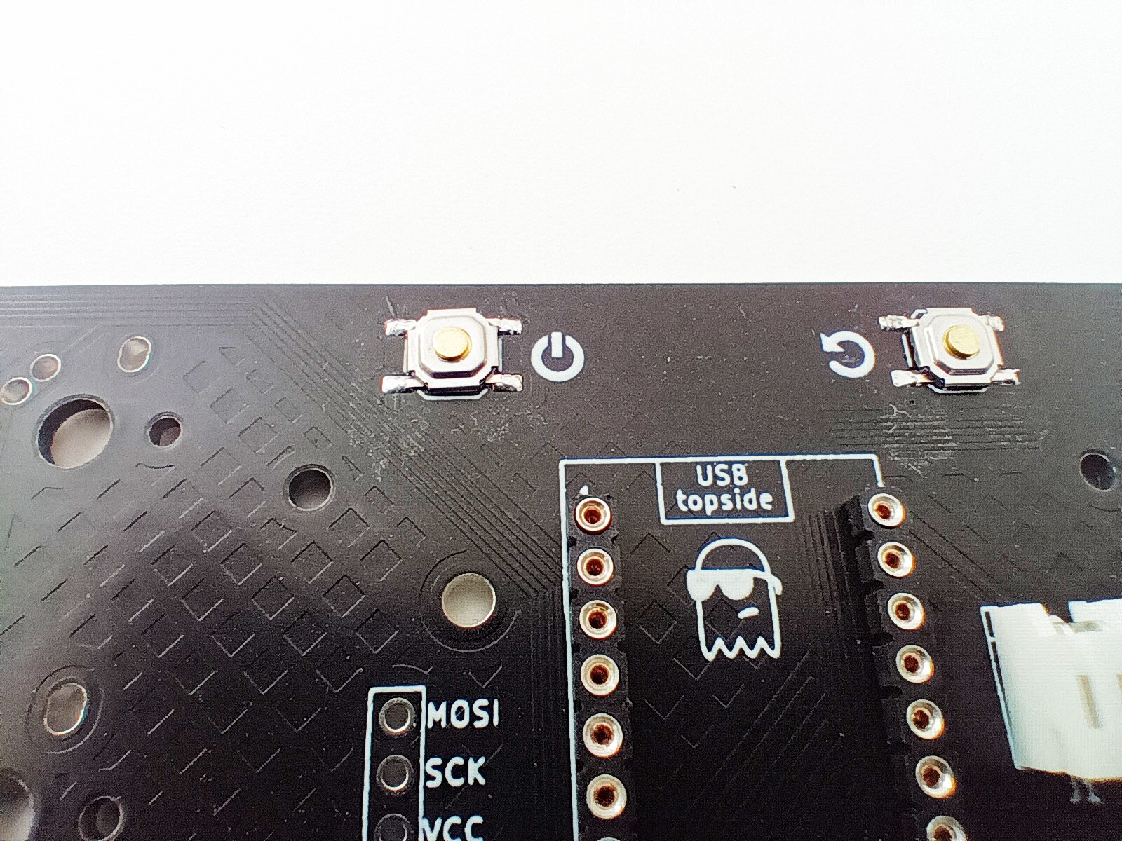
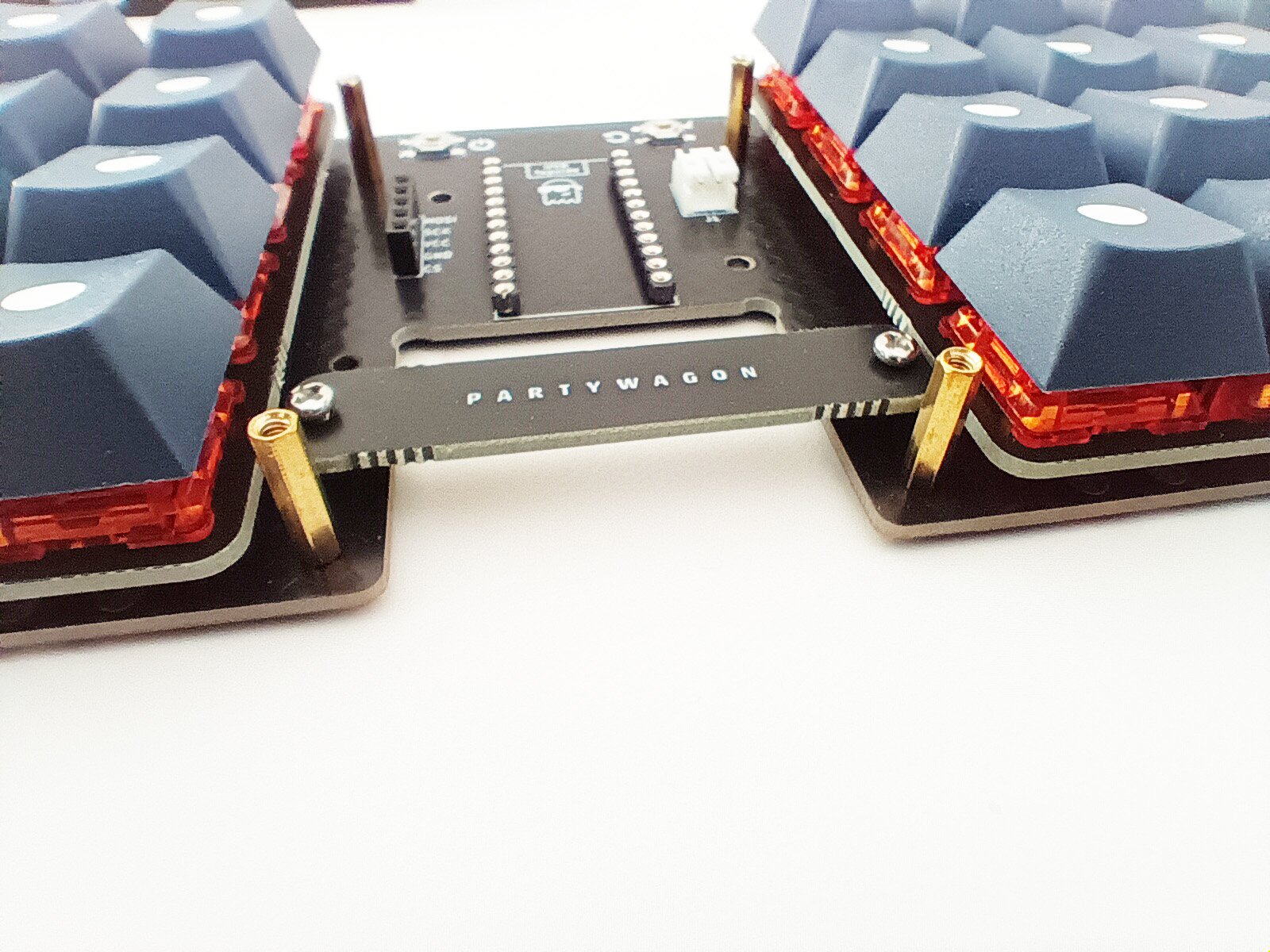
Whether or not you are using the included headers, a total of 6 legs need to be clipped flush with the PCB to create the best possible fit in the keyboard case. Please refer to the images to identify which to clip.
Time to put on the safety glasses / goggles. Holding the header in position, use a pair of side cutters to clip flush the 6 pins that are indicated. The bits that are clipped free tend to shoot away pretty forcefully , so please keep that in mind when planning which direction to point it while trimming.
Verify the correct parts have been removed.
*If you are using Millmax and pins, insert the pins using tweezers. Leave the 6 clipped ones empty for now.
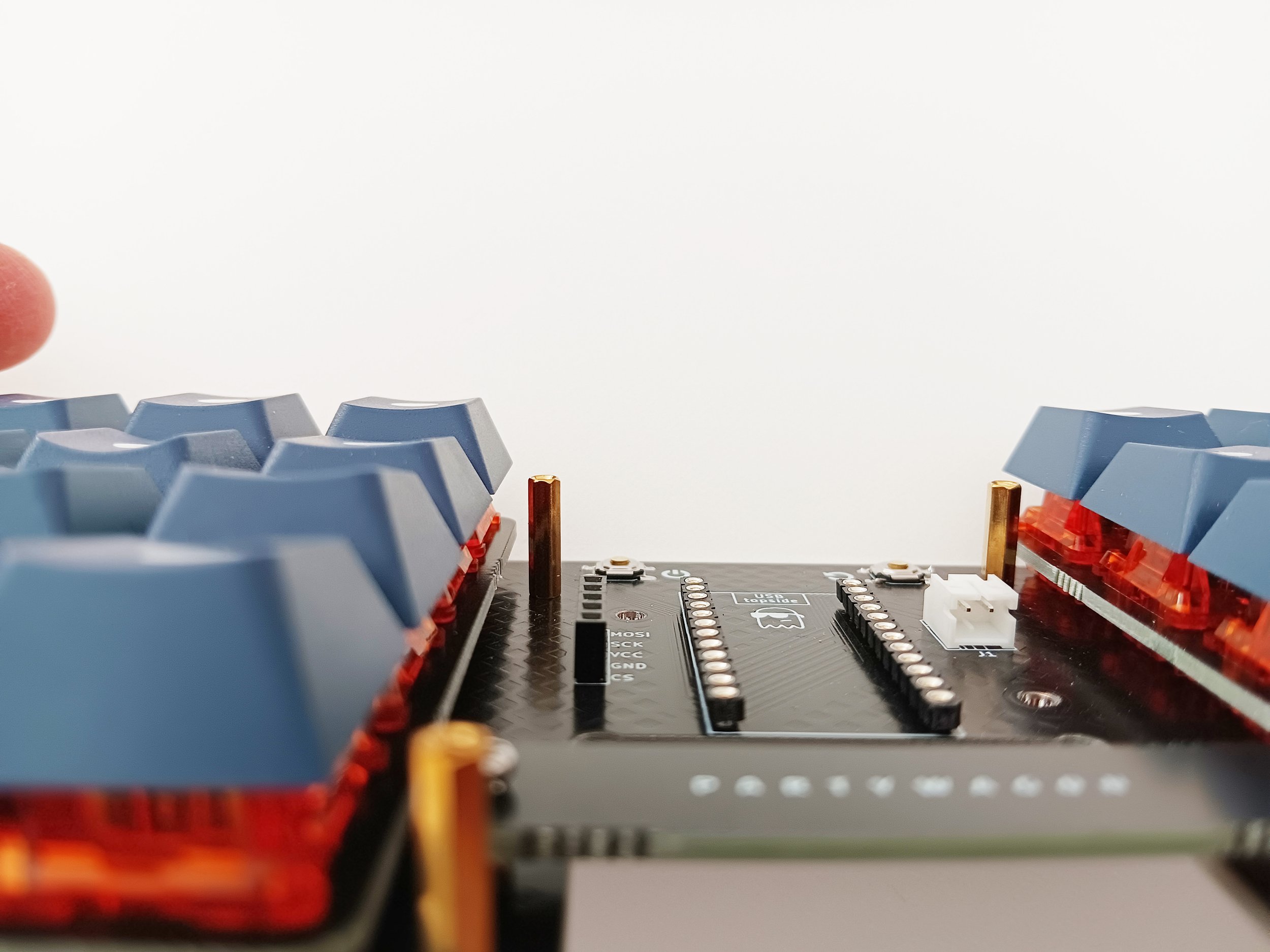
Place the nice!nano onto the headers in the position it will eventually take. Flip the PCB over so you are soldering on the bottom side with the Partywagon logo type. Solder one of the end legs that is full length on each side of the headers. Take a moment to look at how square the installation is going from the top and side. If the headers are not sitting completely against the PCB, use the iron to reheat the soldered pin and push the header into a better seating.
Once the headers are nice and square, continue to solder the remaining full length, unclipped legs. When you only have the flush clipped legs left, apply some flux and use the smallest amount of solder to create the connection, with the goal being a very flat solder plug that will sit nicely on the case supports.
If you are using Millmax and pins, insert the remaining pins using tweezers. If available, place a strip of masking tape along each row of pins. Push the tape so the pins puncture through, and place the nice!nano on top, pushing the tape completely down.
Whether you are using Millmax and pins or the included headers, start by soldering a single pin on each side and then check to make sure the nice!nano is square and flat. If it’s not, then reheat the solder and help press it into place. Make sure to keep your fingers from touching the heated pins/legs. Once you are happy with the position, you can finish soldering the rest of the pins/legs.
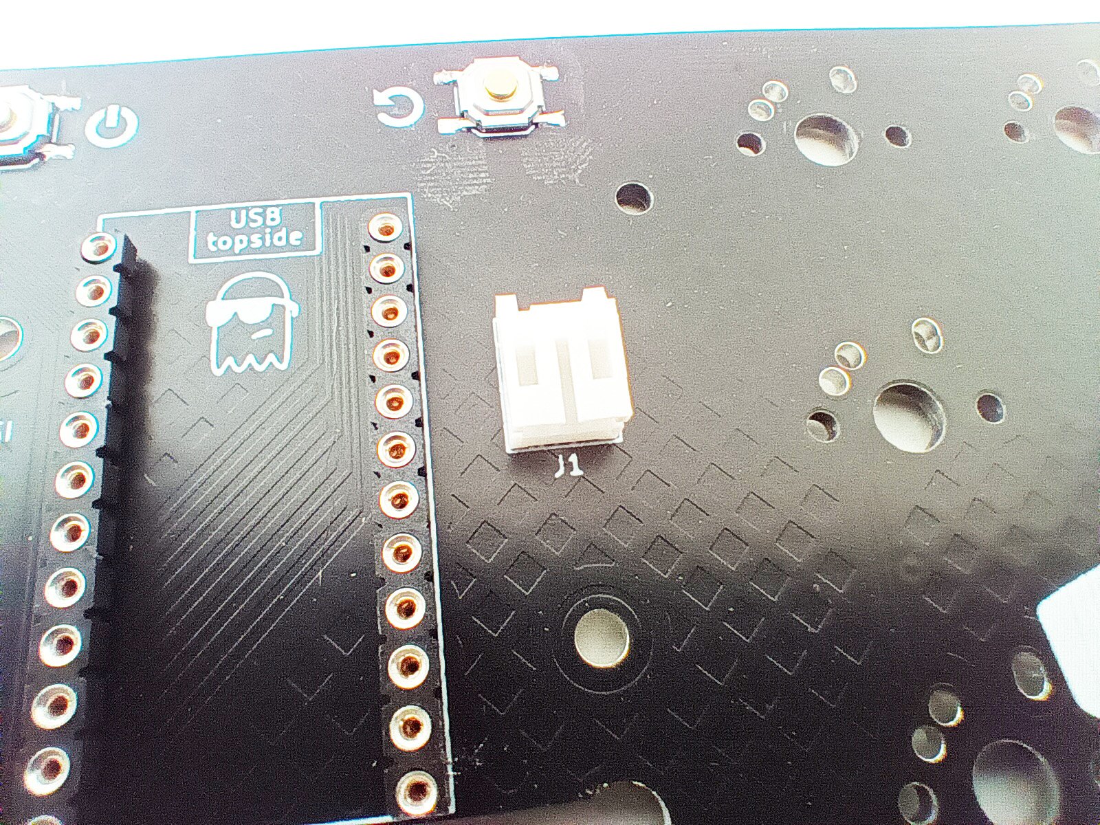
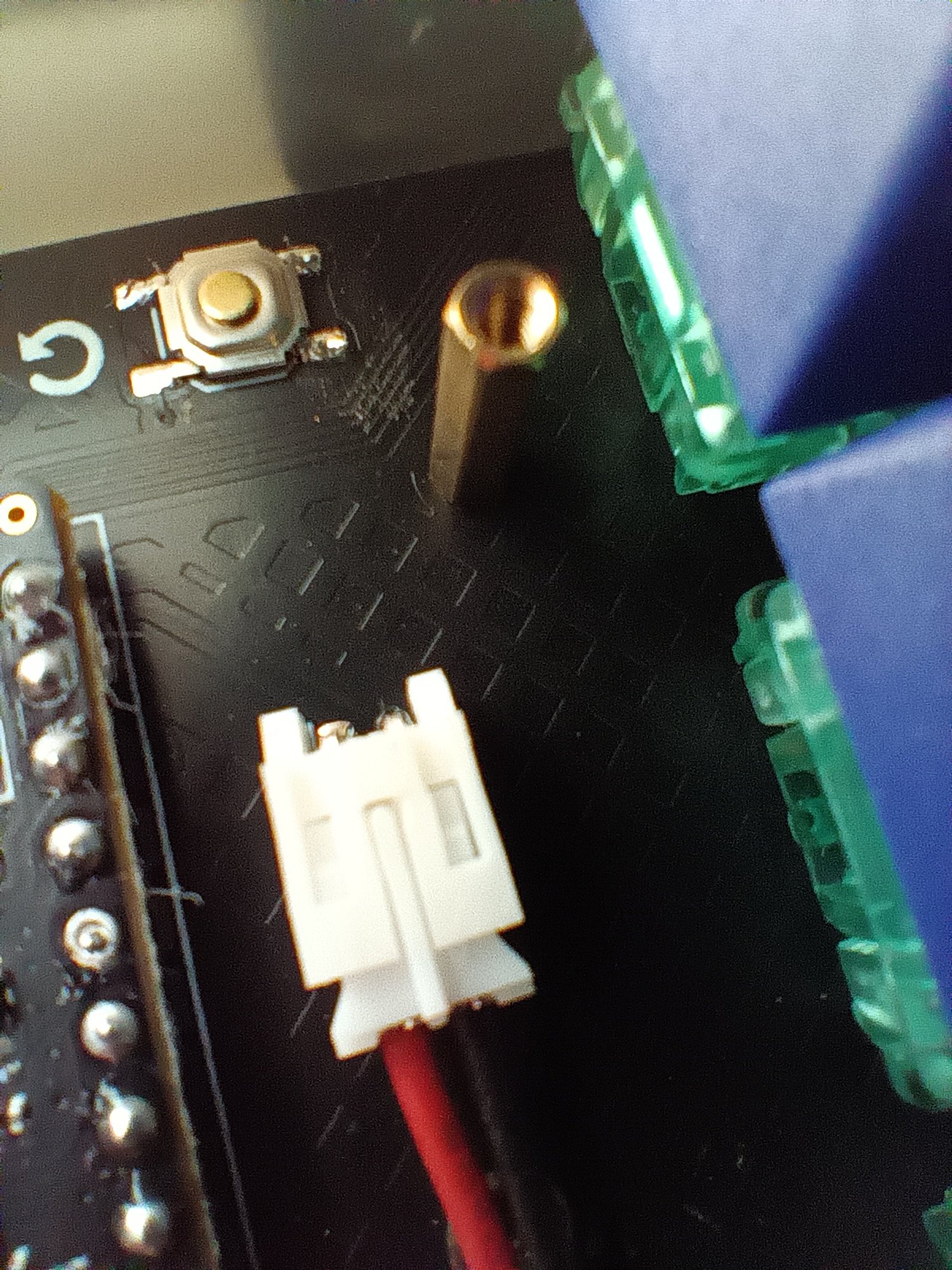
The J1 battery connector is installed on the top side of the PCB, so make sure you can see the sunglasses art and the nice!nano should also be in place now too. The battery connector is installed so it aligns with the drawing on the PCB. Insert the legs with the opening facing down. Apply some flux to the exposed legs on the bottom side of the PCB. Hold it in place and add some solder from your iron, or place something under it while flipping the PCB so it has a support holding it into place while you solder one of the two connections. Check to make sure it’s sitting nicely and proceed to solder the other connection once you are happy.
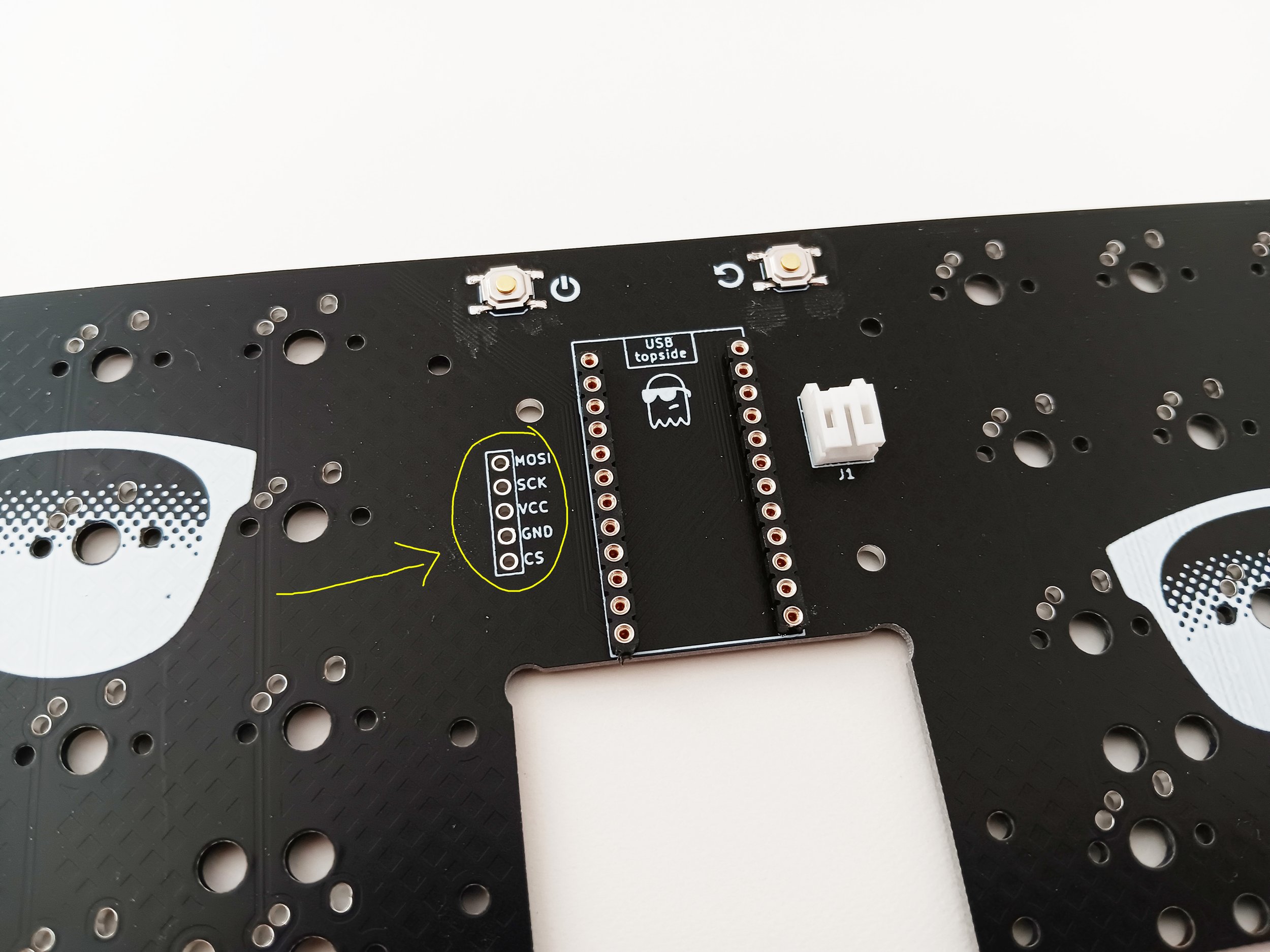
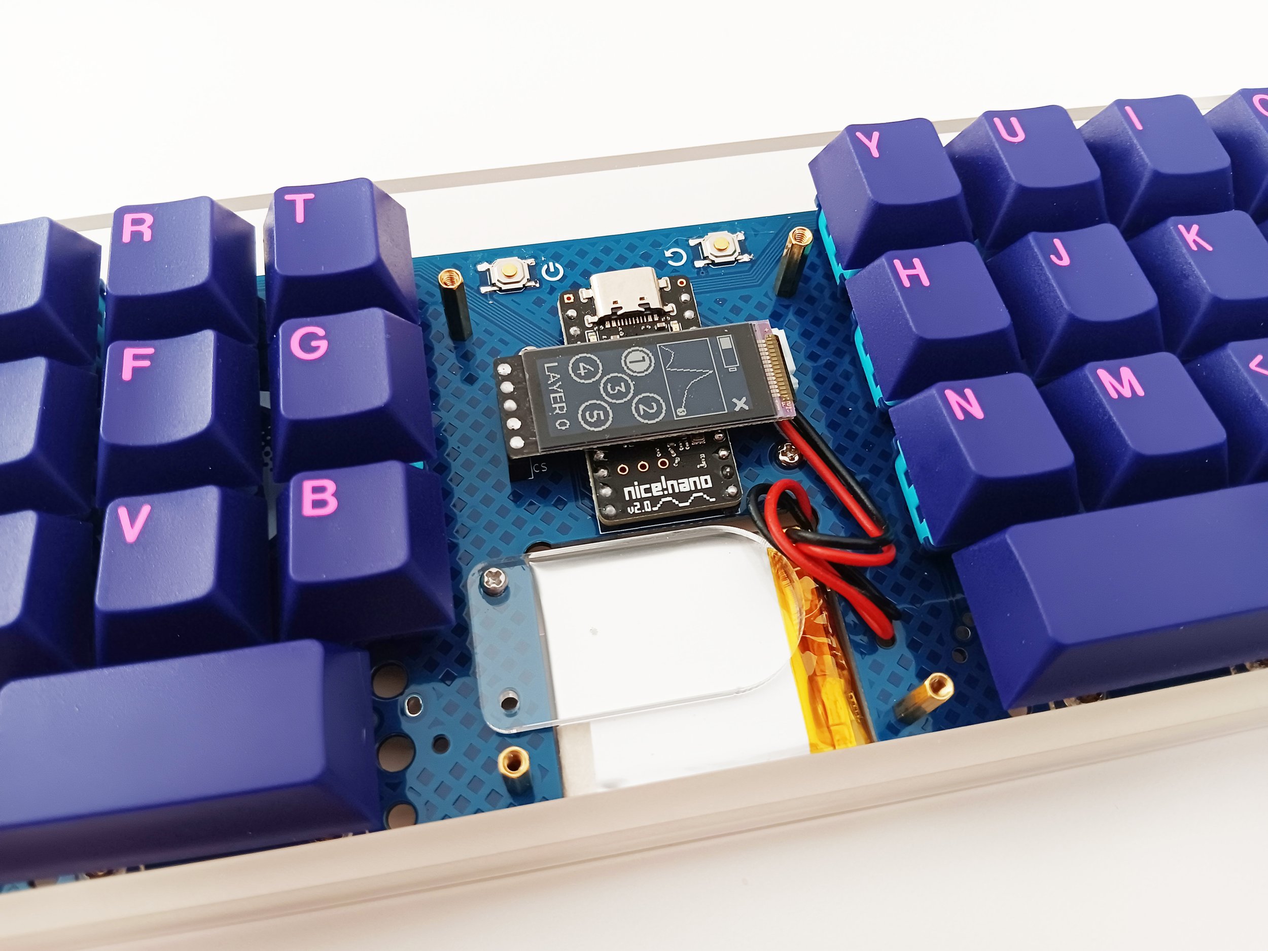
The display header is installed on the top side along with the J1 connector and nice!nano. Use the same process of soldering one leg, checking for alignment, and continuing with the rest once the position looks good. You can wait to insert the screen until the PCB is screwed into the case. (step 14)
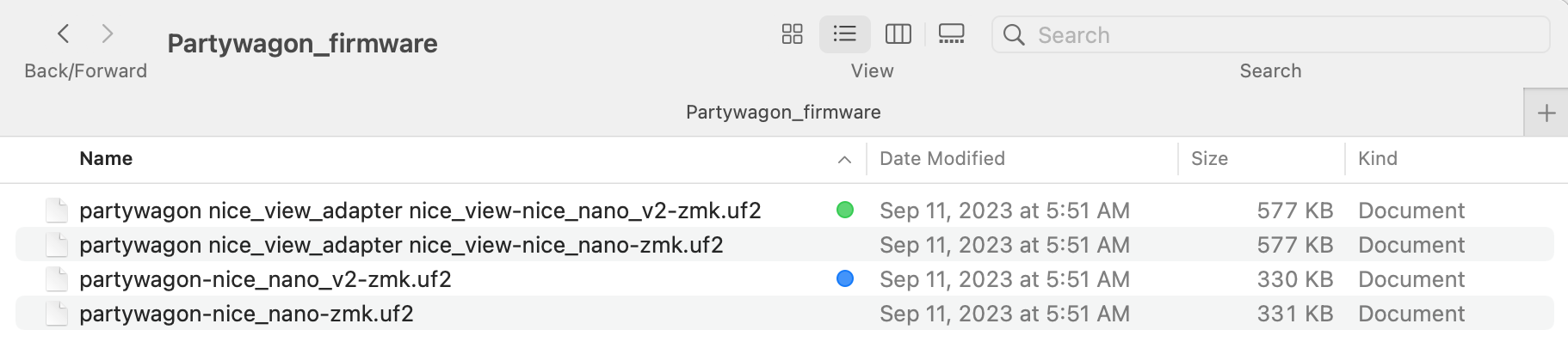
The default firmware can be downloaded from this link.
Flashing it to the nice!nano is as simple as connecting it to your computer with a usb-c cable. For it’s initial programming, it will connect in its bootloader mode automatically. Anytime after the first flash, you can enter bootloader mode by double tapping the reset button quickly, or using the keys assigned to trigger the bootloader mode as illustrated on the default keymap guide. (Layer 3 - the same key as “a“ or the apostrophe key)
Once you see the nice!nano pop up as a connected device, you can drag the .UF2 into the folder to start the autoflashing. When it’s done, it will disconnect on it’s own. Finish by restarting the keyboard with the reset button.
It is now a good time to test and see if the diodes are all mounted well. While connected to a computer, work your way through each switch’s location and bridge the connection with your tweezers. The corresponding keypress should register in your text editor or browser bar or wherever it’s convenient to test out. If you find a key that is not registering, take a close look at the associated diode, and even if it looks fine, it’s worth taking the soldering iron and flux and making sure that the diode is connected well to both pads on the PCB.
Short article about stabilizers and tuning.
Install any stabilizers that you plan on using. They are centered one row below the traditional “v“ and “m“ positions. Only clip-in PCB mount style stabilizers are supported.
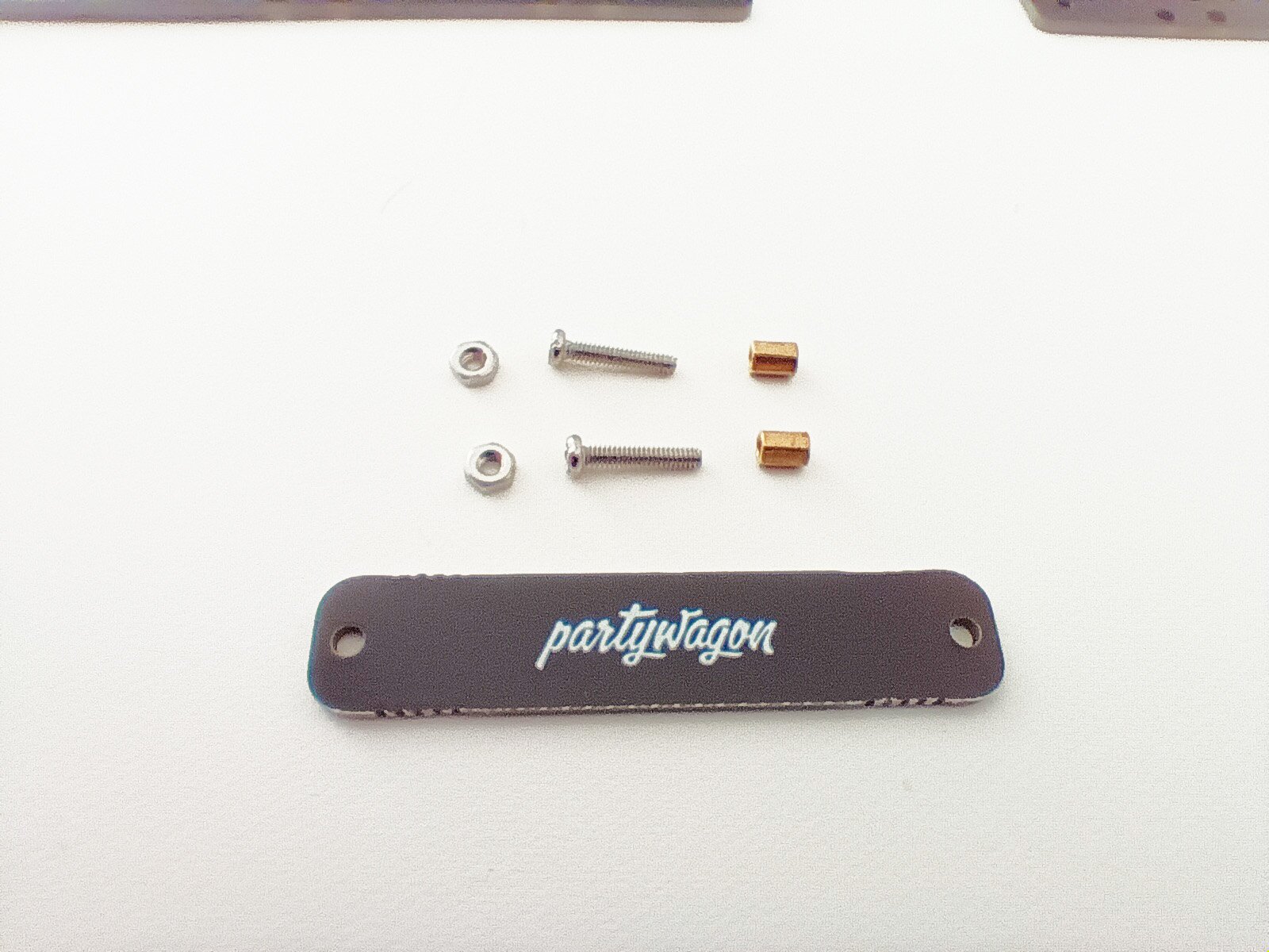
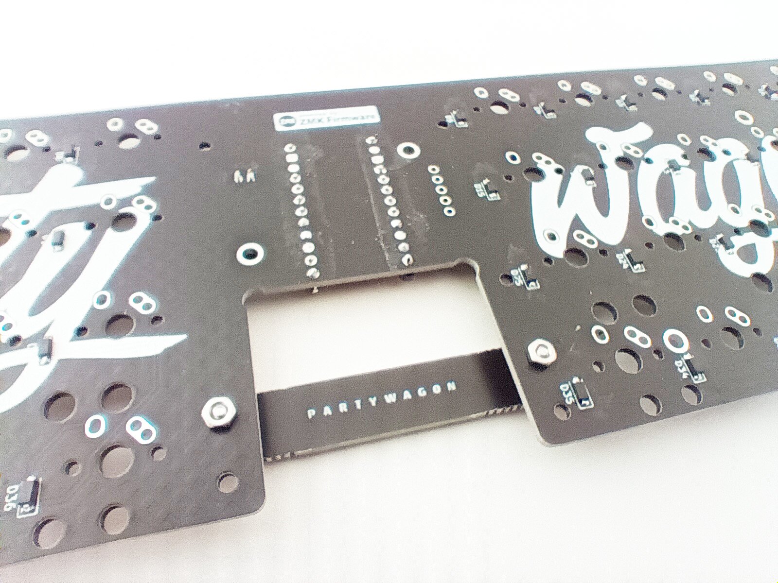
Separate the battery retention bar from the switch plates by clipping with sidecutters along the mouse bites perforation holes. You can smooth the mouse bites area with additional passes of the sidecutter blades or with a file. Choose which logo will be displayed.
It is a bit easier to get to these mounting holes while the key switches are not installed, but if you skip this and come back, it is still quite simple to finish.
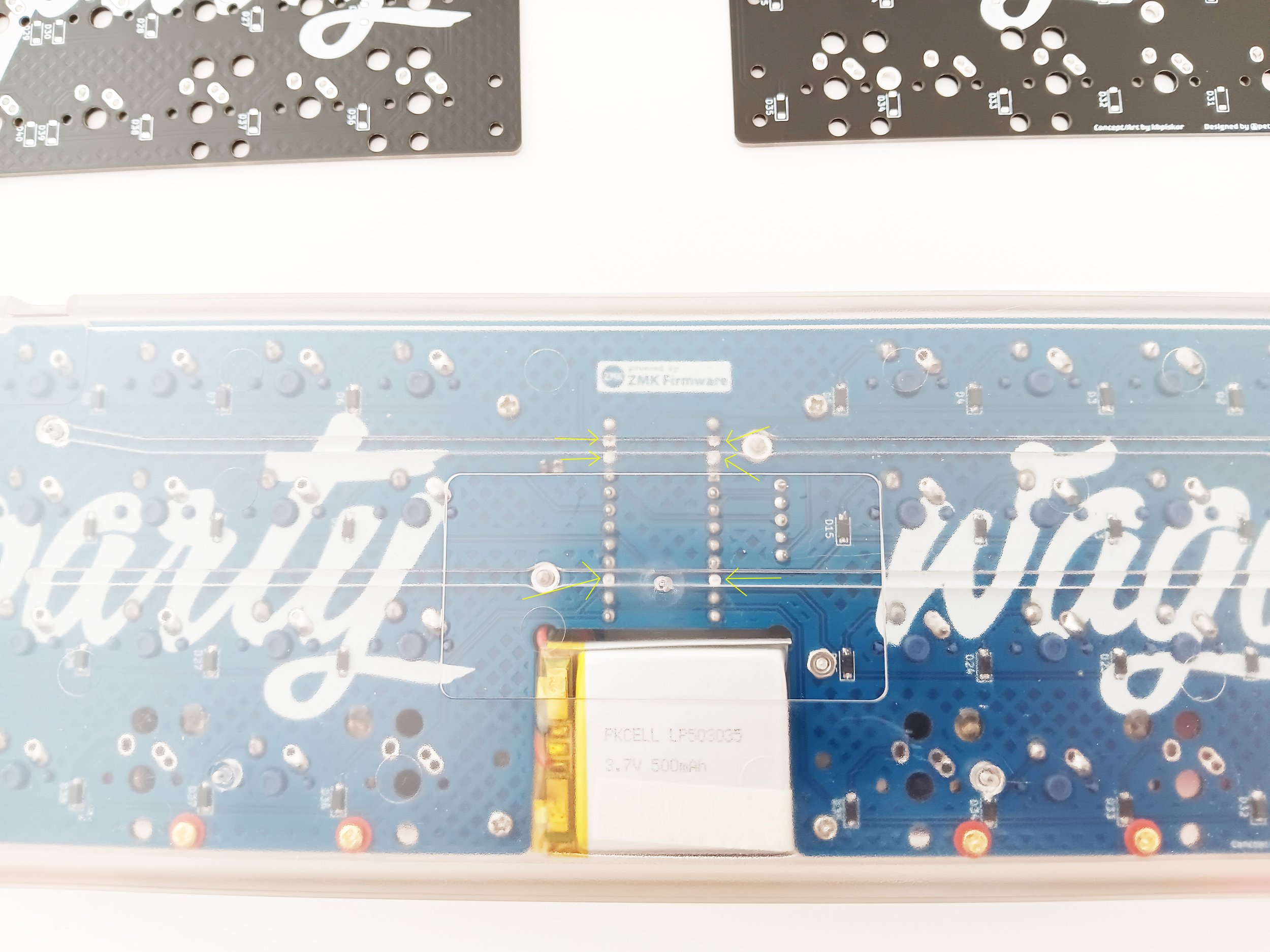
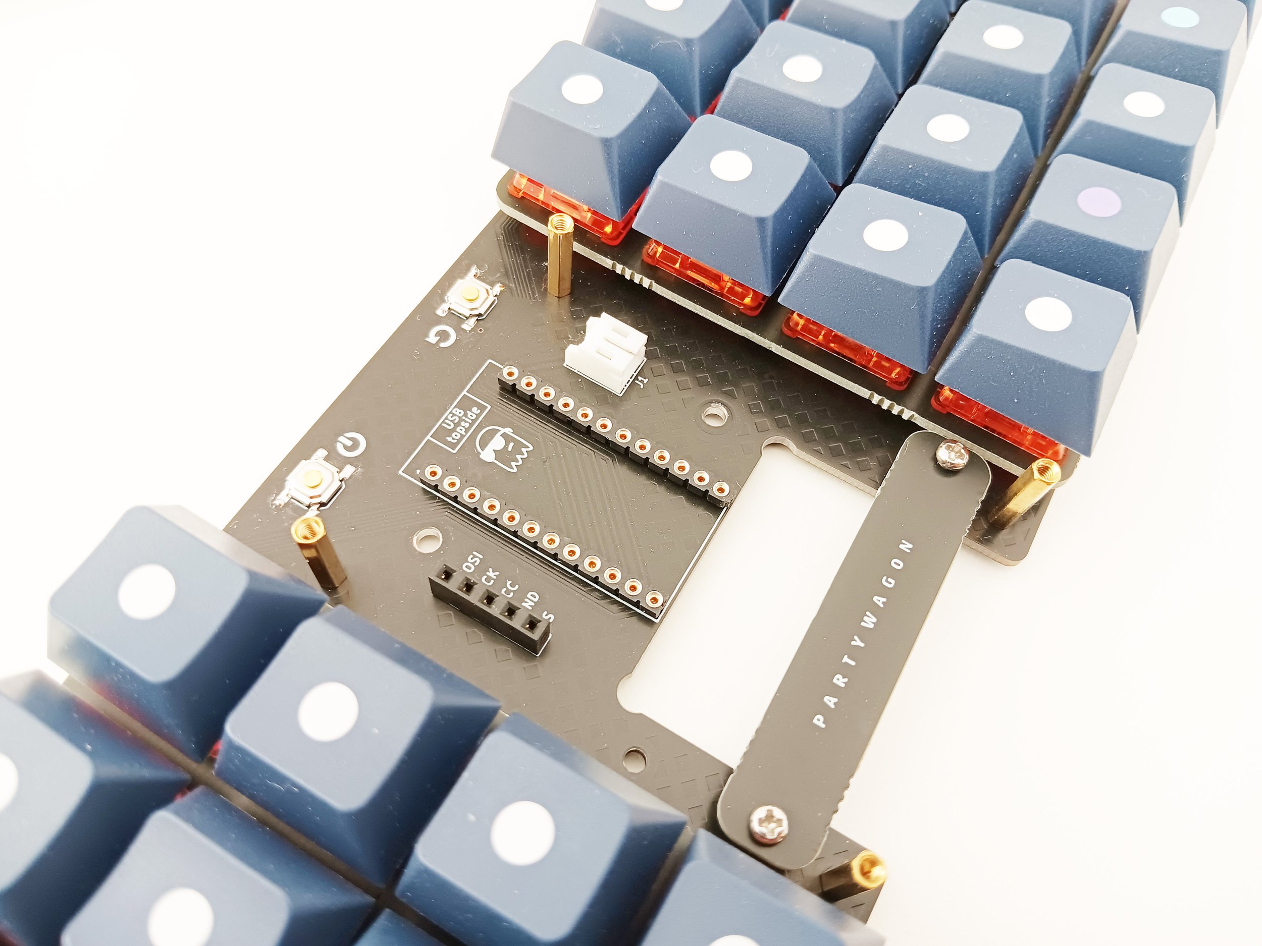
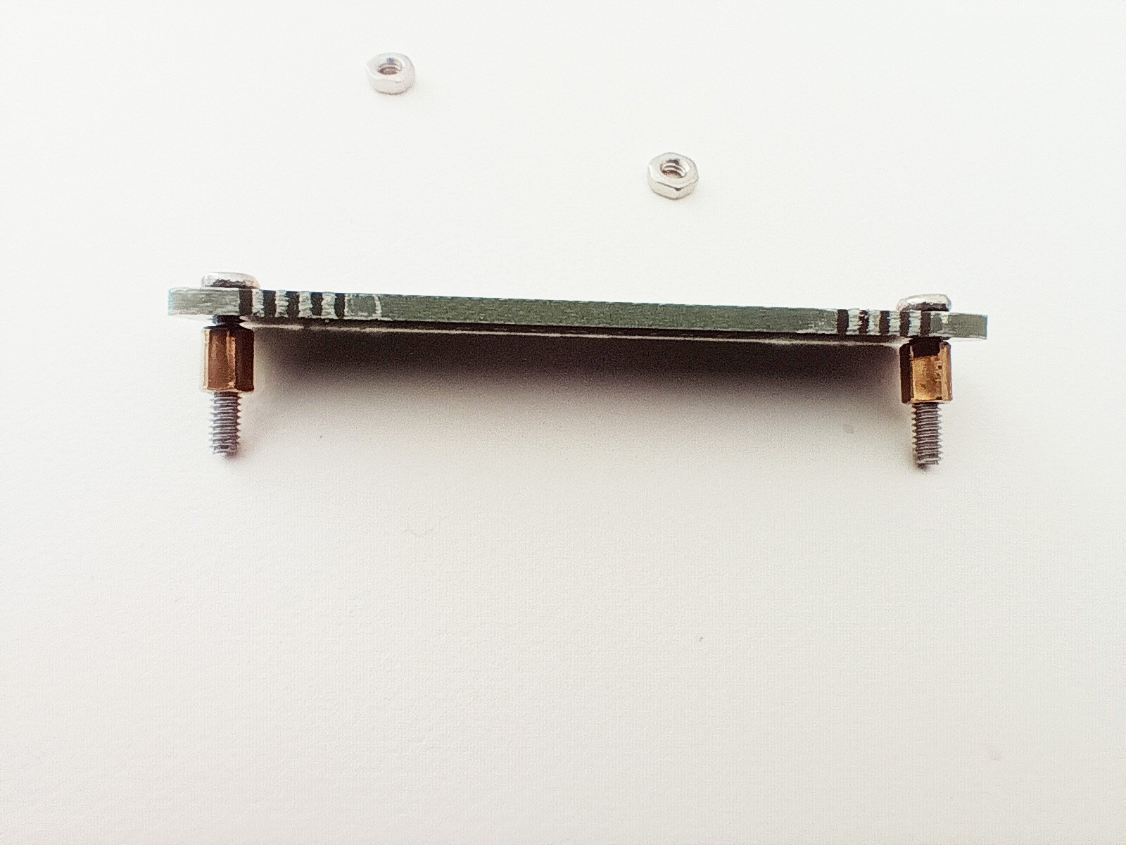
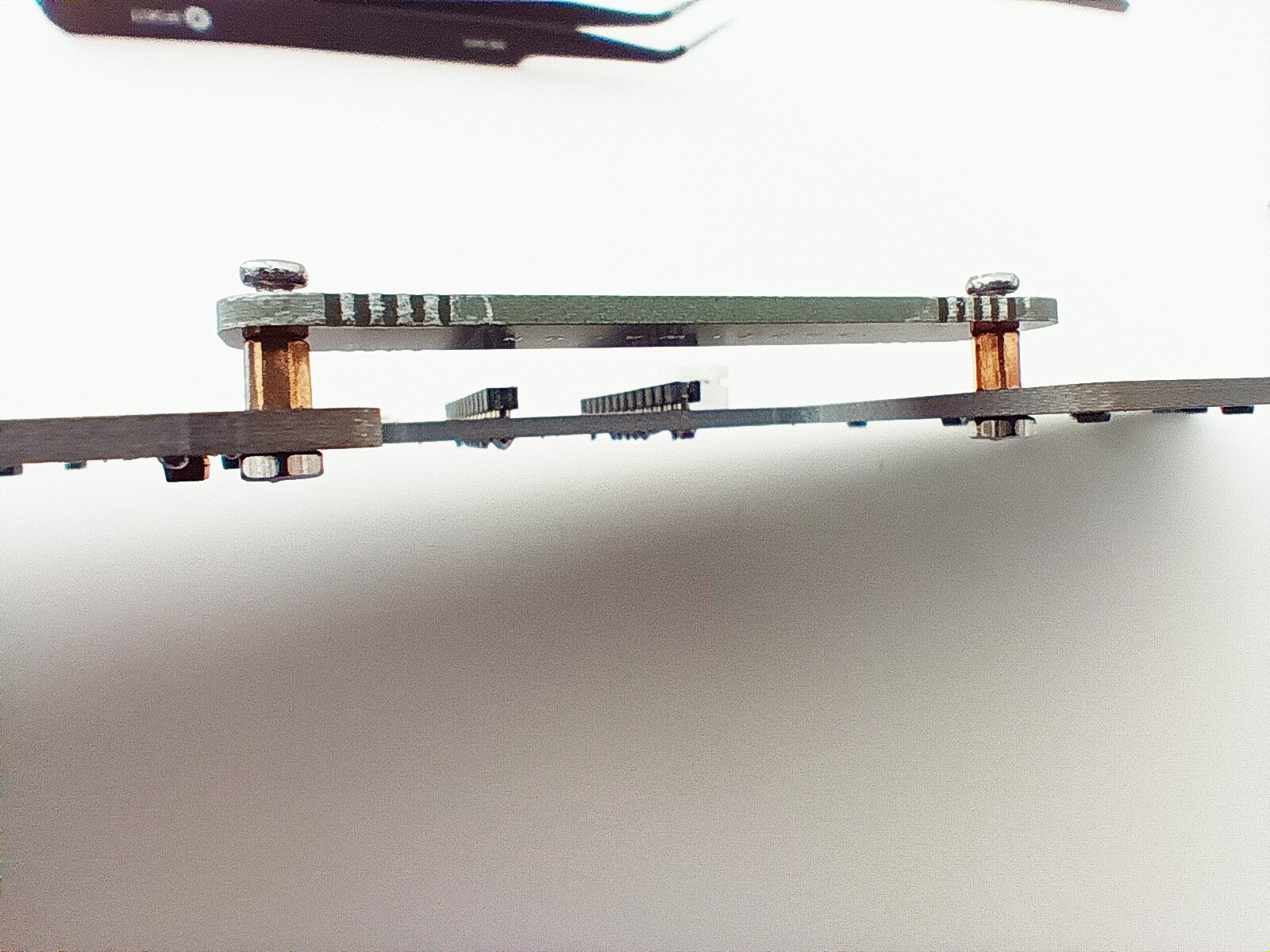
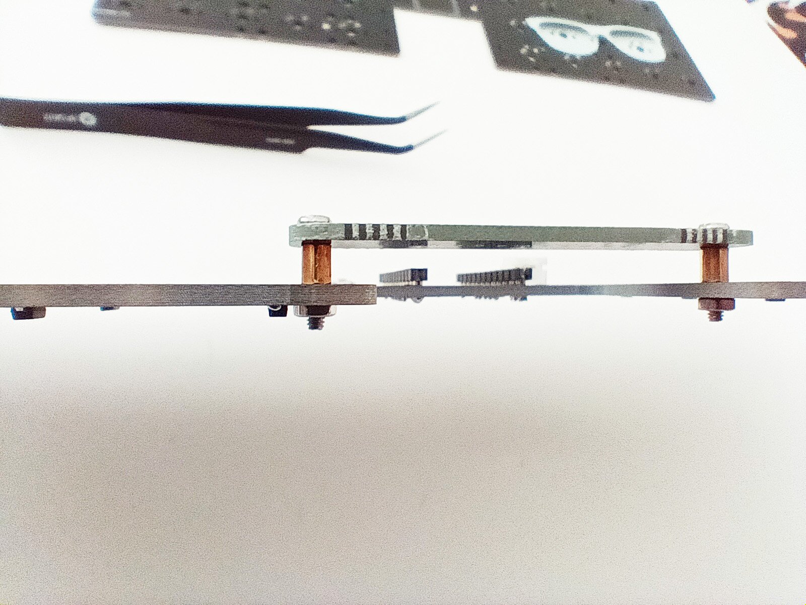
Take the two shortest spacers and the two longest screws and sandwich the battery bar like demonstrated in the image. Do not tighten it completely - a little play now will help with the PCB mount.
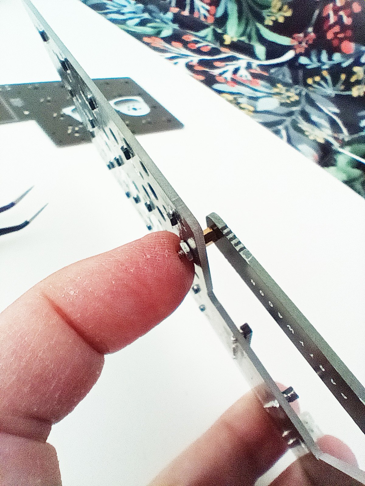
Mount the bar sandwich to the PCB and add the nuts to the back. Finger-tighten as possible. Place a finger on the nut to hold it in place and use a screwdriver to tighten fully. Repeat on the other side.
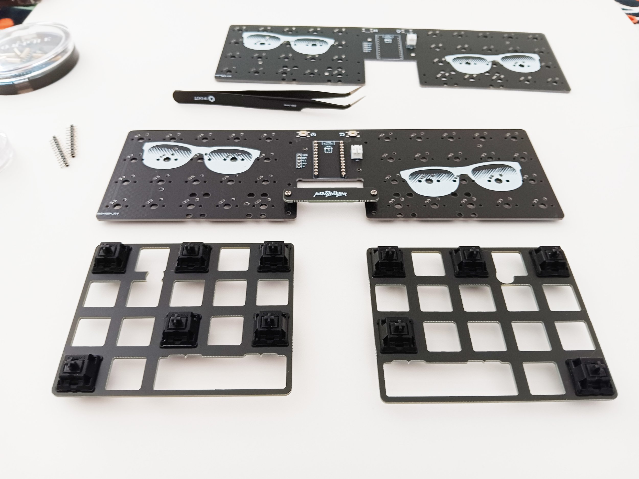
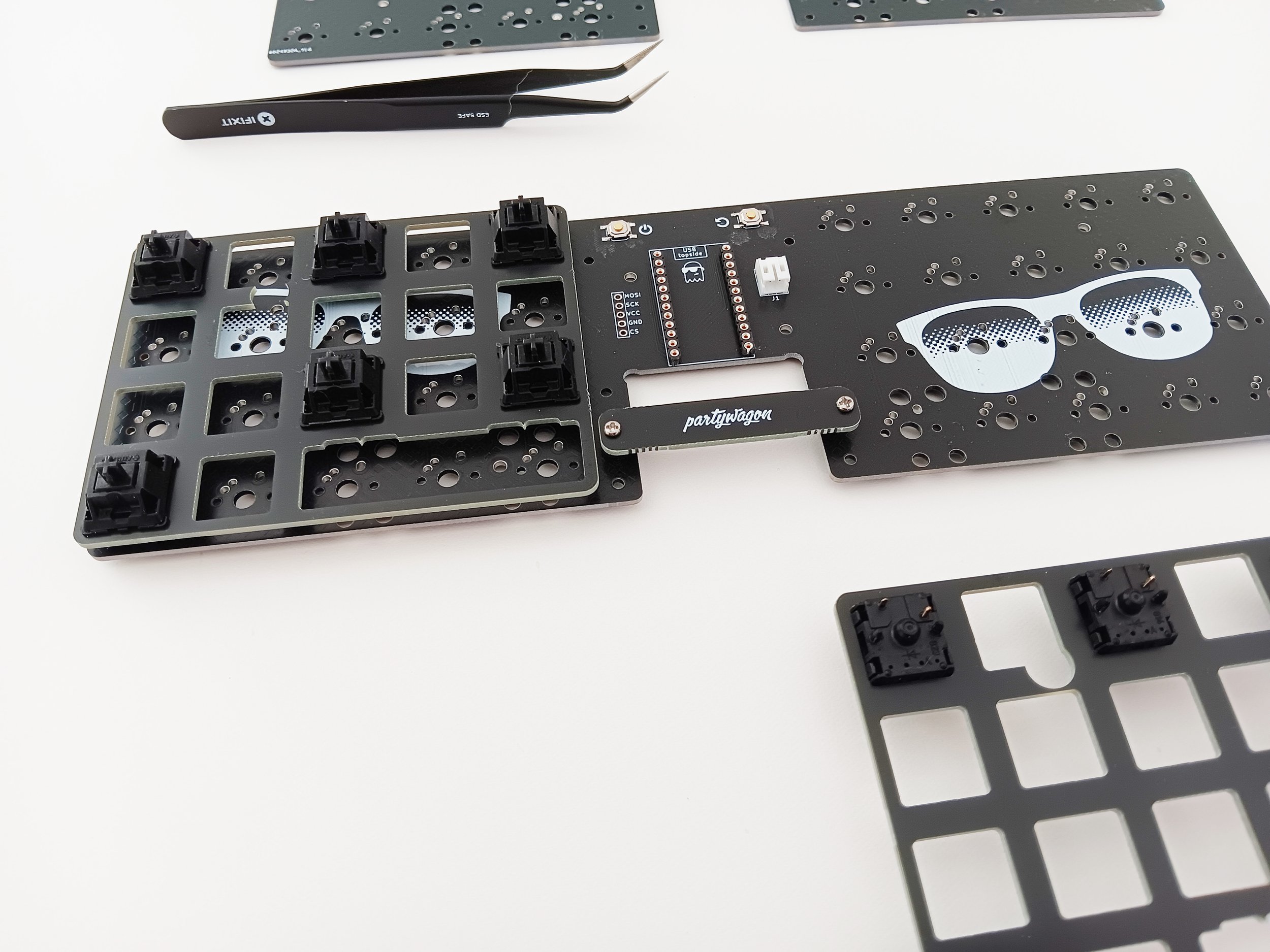
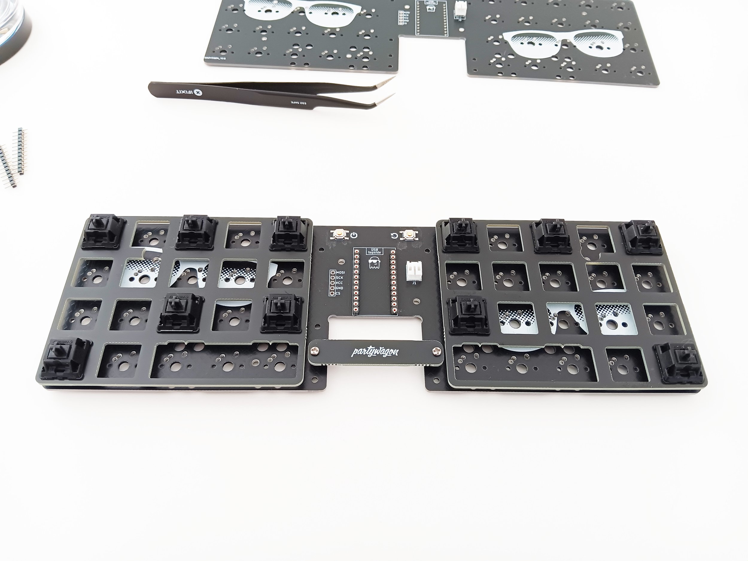
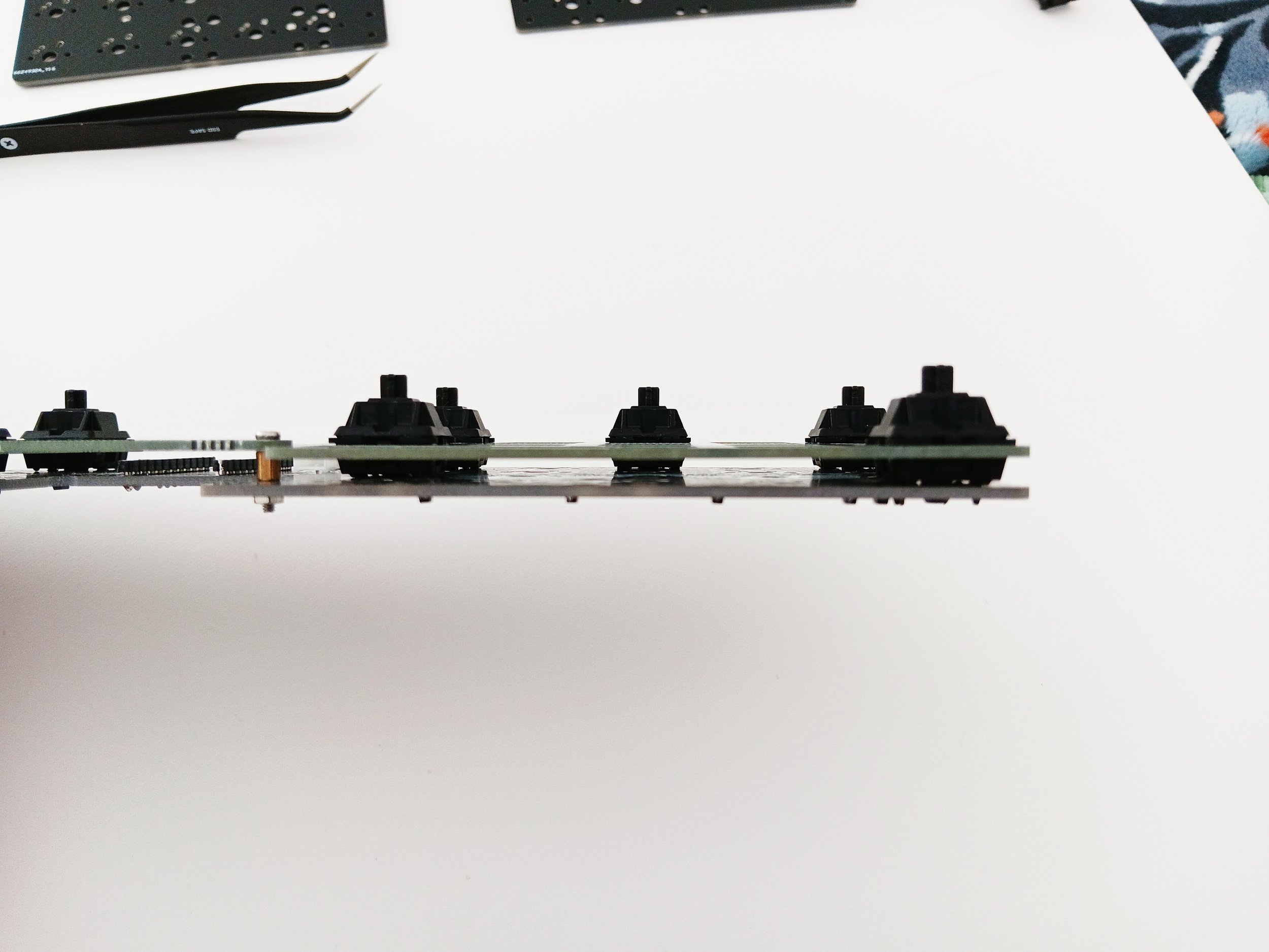
The switched are installed on the top side of the PCB (with sunglasses art). Decide whether you will be using the switch plates. The PCB will support a no-plate build, but I would recommend sticking with 5-pin switches when building this way.
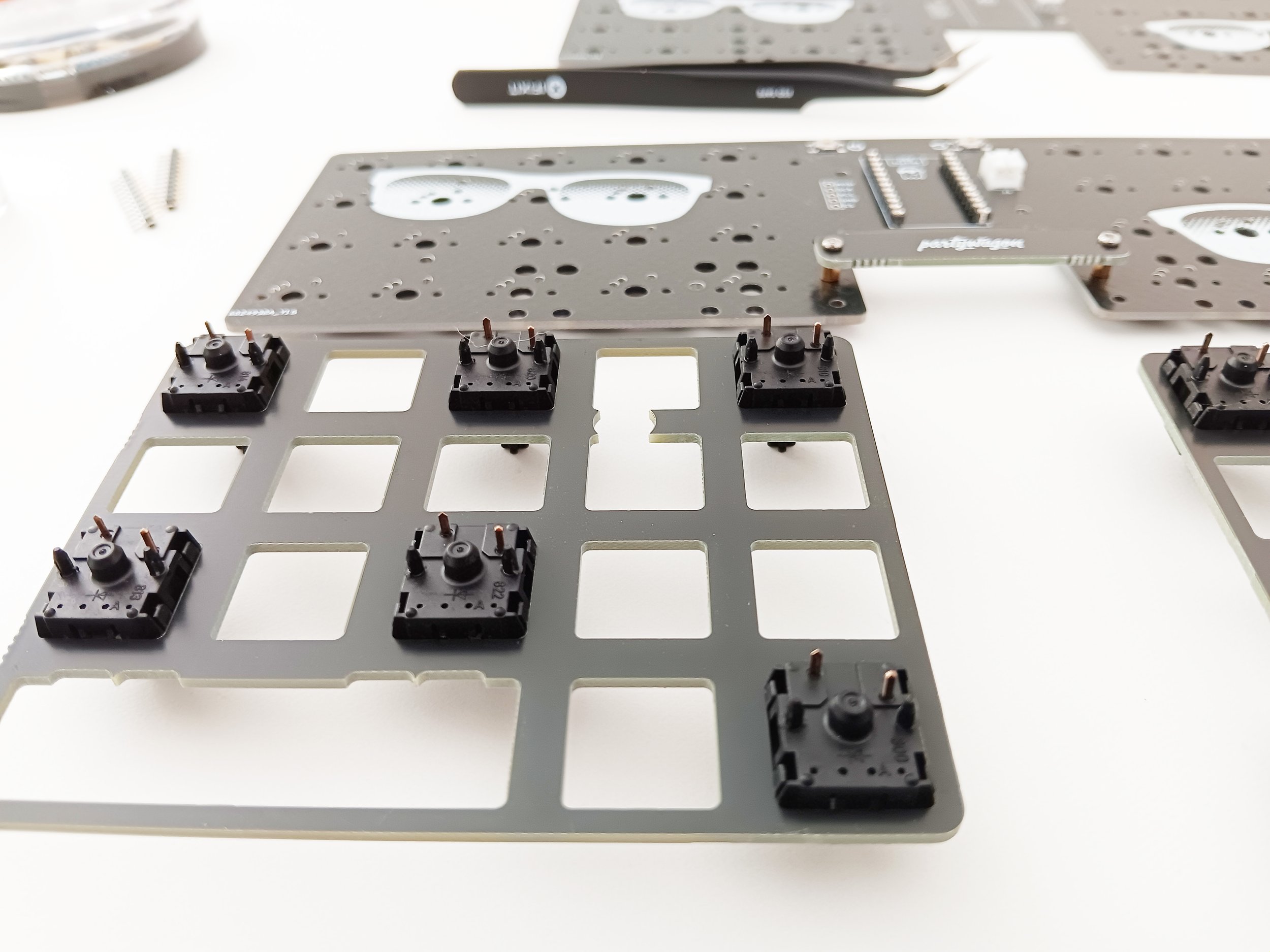
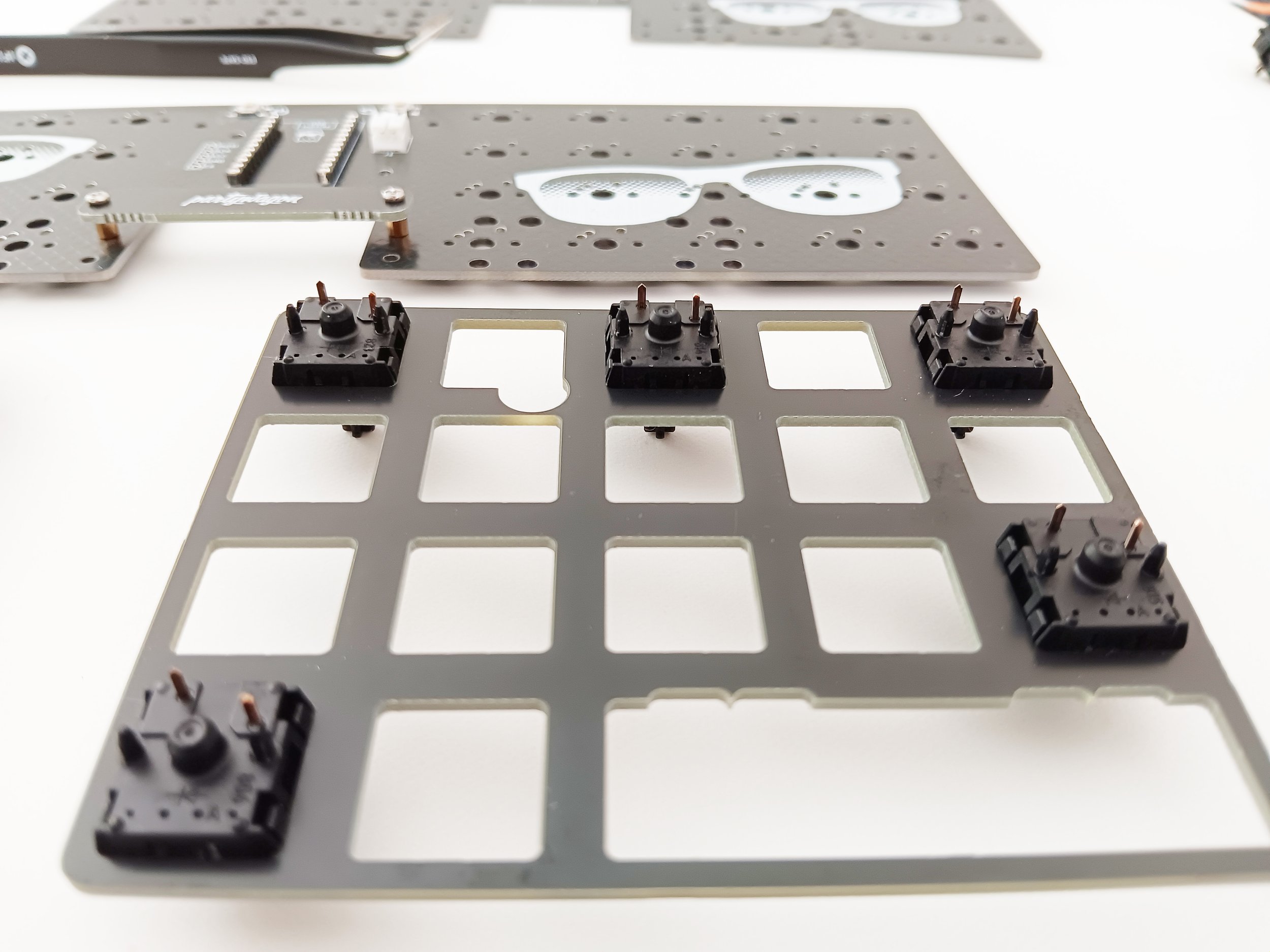
Check the pins on your switches to make sure they are all pretty straight. Fix any bent pins with your tweezers if possible.
If you are not using plates - install the switches so the pins fit correctly, and double-check they are all fully seated and pressed in.
If you are using plates - put a switch in each corner of the switch plates and then press into place onto the PCB. You can also put all the switches in the plates and install them simultaneously, but it takes more hand strength and more repeated pressing until everything has fully seated.
Flip it over and solder each switches pins leaving a good size lump in place. Double-check that none were missed.
This is a great time to check your work (and diode function) by connecting it to a computer and trying to register each of the keys. If you find any not responding, go back to the diode and make sure it is oriented the right way. Then resolder/add solder as needed.

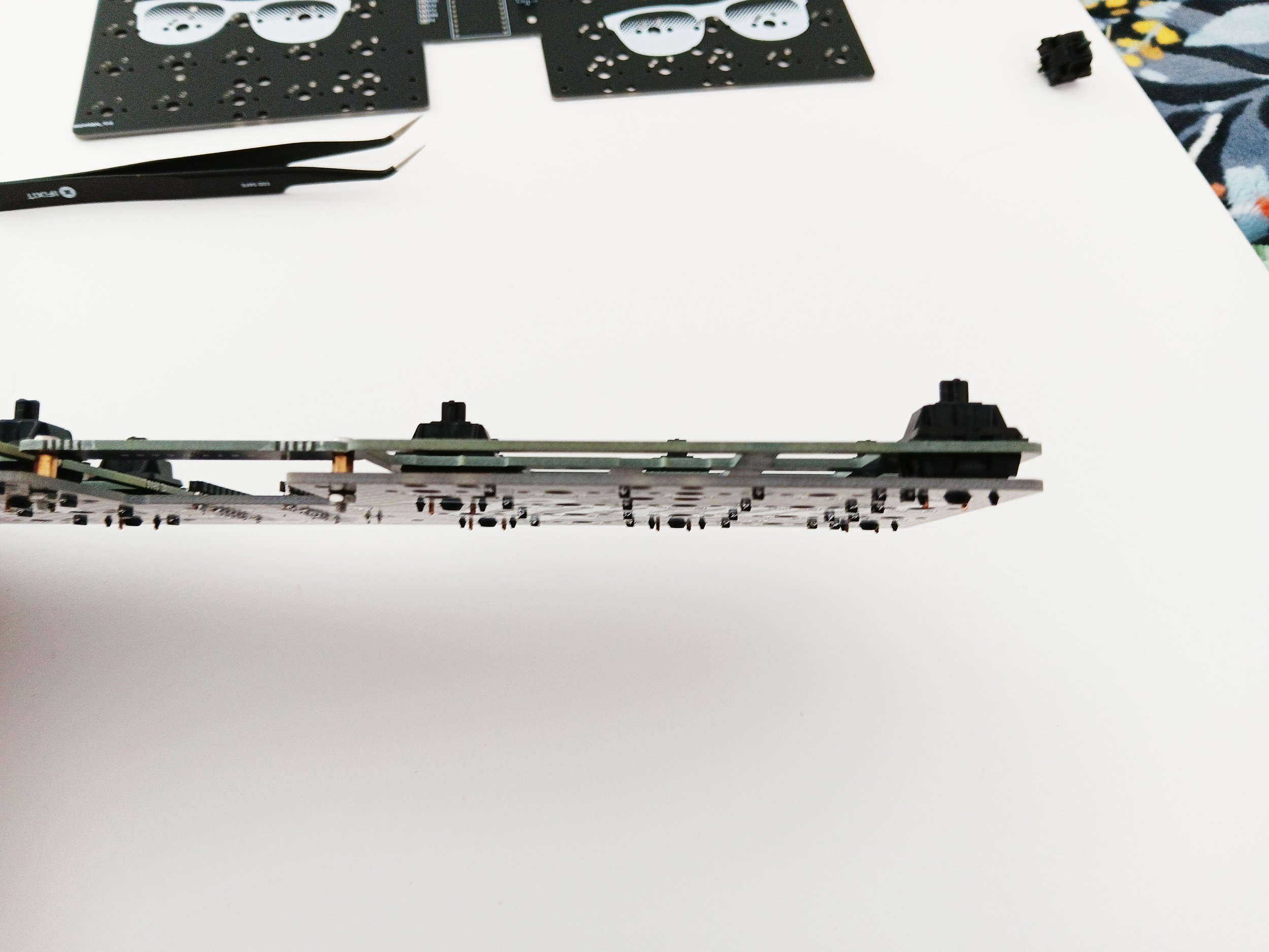
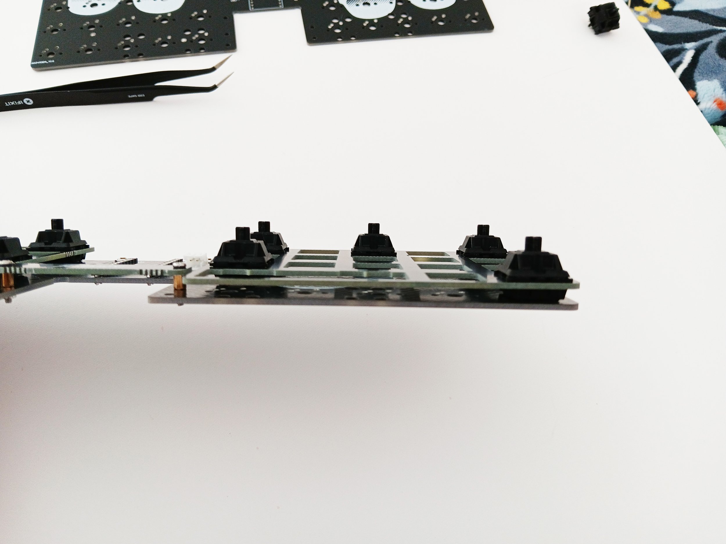
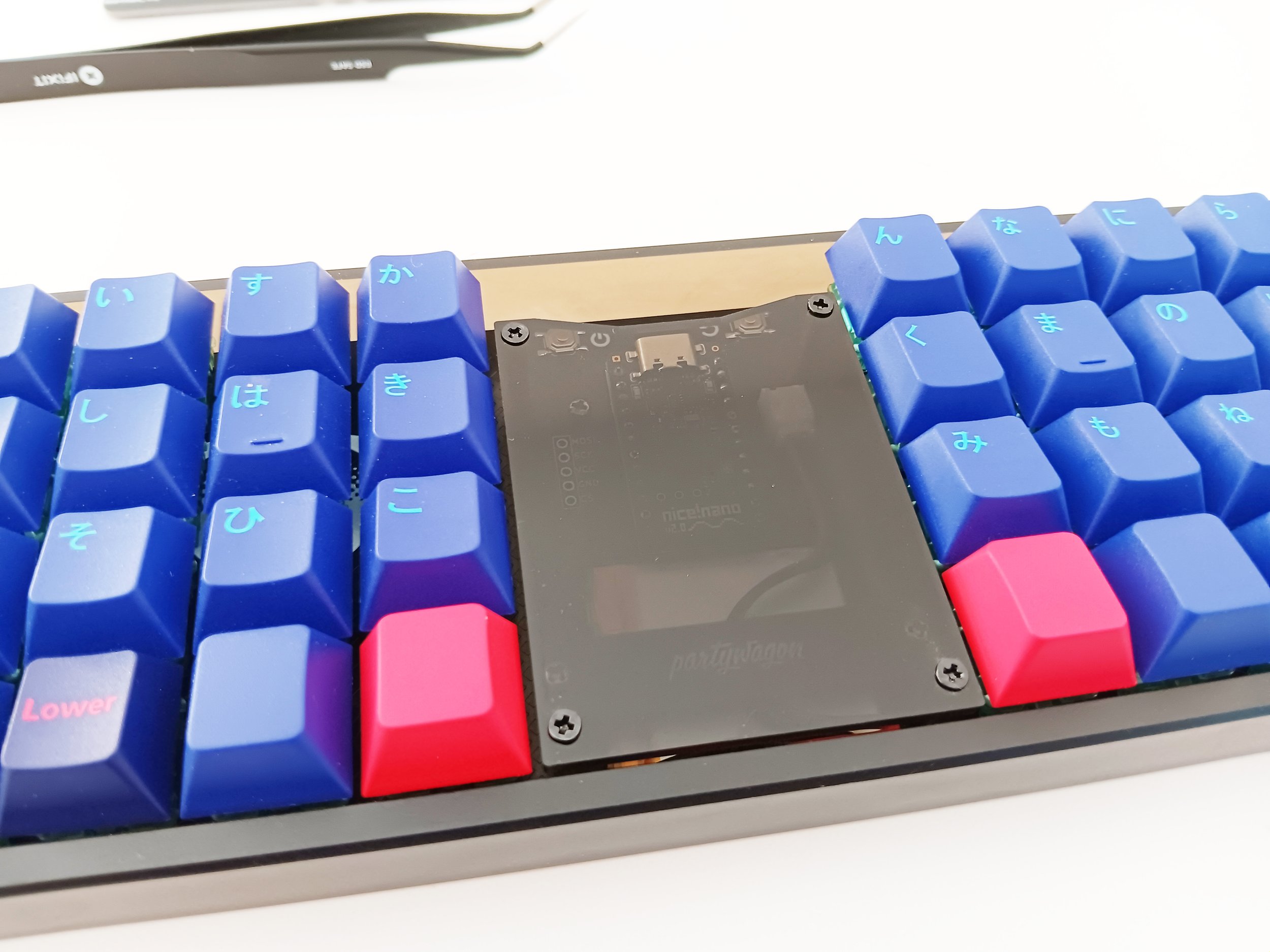
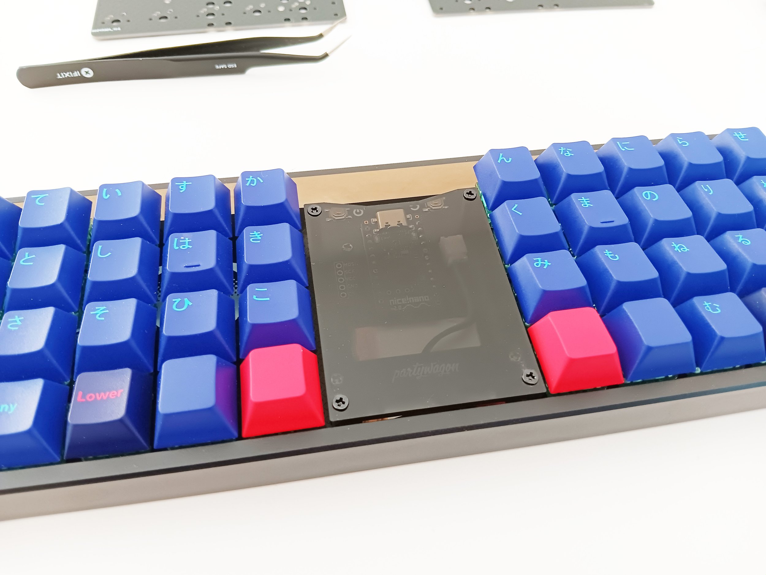
Use the four longer spacers and four of the shorter screws to install the acrylic cover supports.
Take note of the battery connector and the rib along one side that slots into the J1 connector at the top. Test fit the battery and decide what you would like to do with the wire. It can be looped and held between the battery bar pretty easily. When happy with your plan, gently push the battery connector into the J1 while also supporting it with a finger. The spudger can help with getting the battery connector aligned corrctly. Push it fully in.
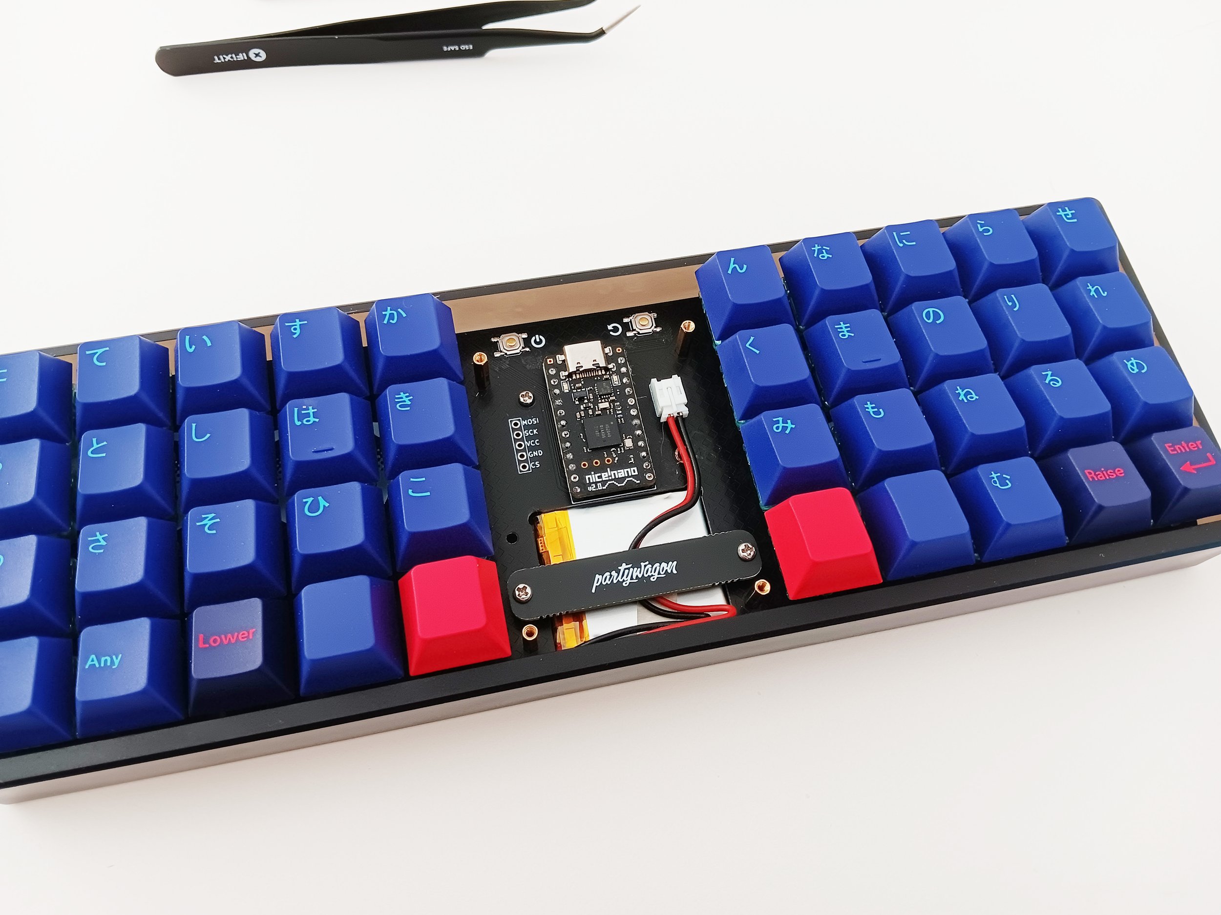
If you are using a coffeebreak minivan case, you may want to add the cork feet to the bottom of the case before securing the PCB to the interior. This could also be a good time to add the Partywagon sticker to the recessed area in the center of the case bottom.
It can help to get everything into the case if you place the PCB switch side down on a table and position the battery in a way you like, then place the case onto the PCB like a hat or cake cover. Grab the whole thing and flip it over so the switches are now facing up. Locate the two mounting holes in the center and one more between the “w“ and “s“. There is a fourth under the “o“, but to use it means removing some of your switch with clippers, and I don’t find it to be necessary at all.
Use some of the shorter screws to secure it to the case.
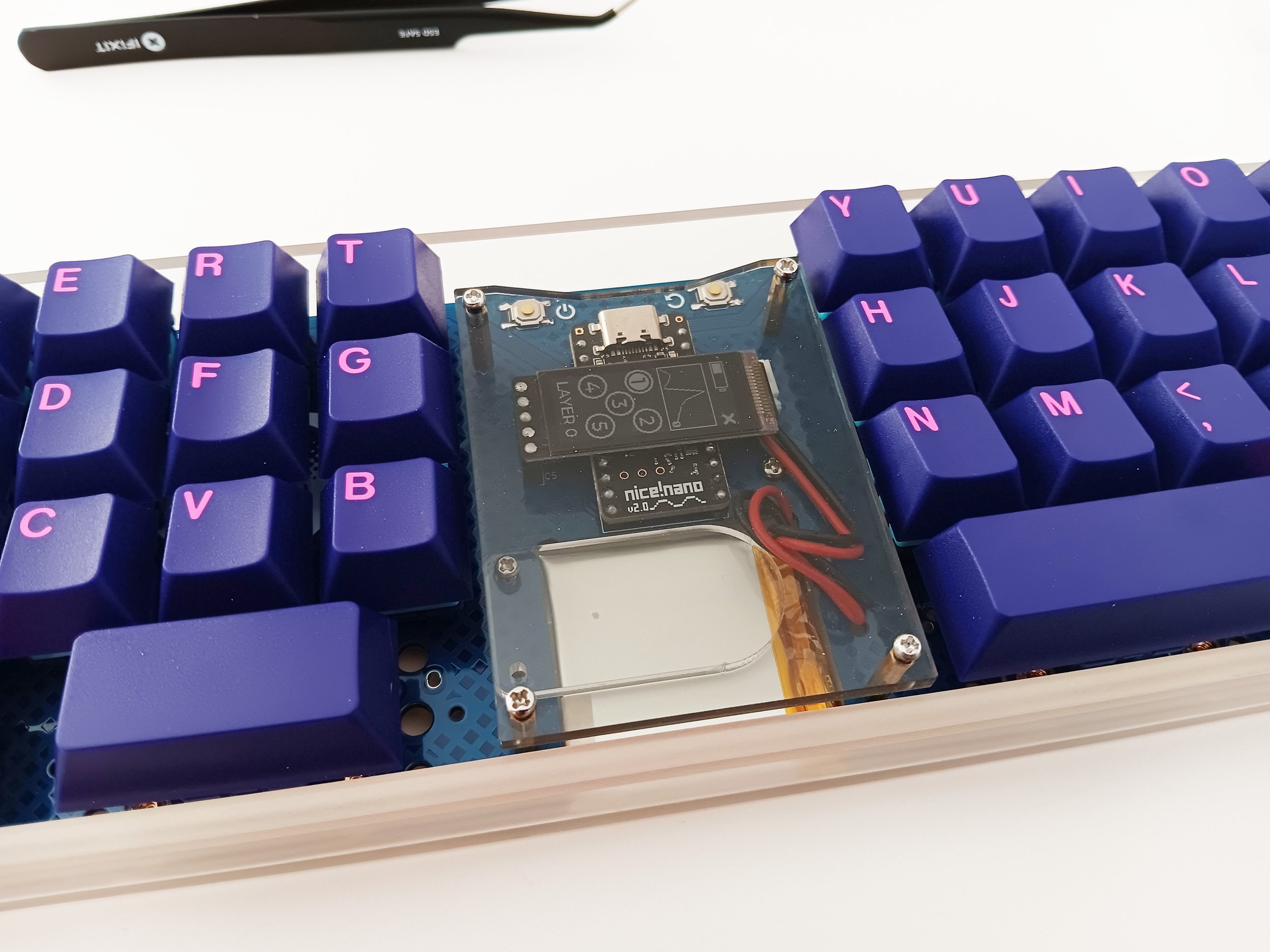
Use four more of the shorter screws to secure the acrylic cover to the top of the spacer supports. The notch side of the cover should face north, so the usb connector can be more easily accessed.
Let your personal style guide you when adding keycaps.